Results
User Interaction
As user interactivity is a core component of our project, we want the interaction experience to be as intuitive and seamless as possible. We used a combination of toggle switches, buttons, and mouse for user inputs. The user interface has been tested extensively through visual inspections by our team members. The usability has been confirmed by the course instructors as well as members from other teams.

The function mapped to each input is listed below along with the timestamp demonstrating it in the video above.
SW0: initialization mode - random particles [0:0]SW1: initialization mode - railgun beam through slit [0:14]SW2: initialization mode - particles at center [0:33]SW3: direction of particle generation - right [0:52]SW4: direction of particle generation - left [1:01]SW5: direction of particle generation - up [1:27]SW6: direction of particle generation - down [1:36]SW7: direction of particle generation - three sides [1:42]SW8: direction of particle generation - two sidesSW9: direction of particle generation - four sides [1:39]KEY0: system resetKEY1: pause animation [5:00]KEY2: artist mode [4:55]KEY3: enable resize mouse cursor; middle mouse button - increase size [3:37]; right mouse button - decrease size [3:06]Mouse-left: add particles [3:41]Mouse-middle: add obstacles [3:12]Mouse-right: clear particles and obstacles [4:27]
Rendering Quality
Our system is able to maintain the 60Hz frame rate with no visible pause or flicker in all situations, regardless of the number of particles currently on screen and whether there's an active user input. When sufficient particles are added to the grid, the simulation behaves as propagating waves instead of individual moving particles. In addition, we observed that regardless of the initial conditions, after a sufficiently long time, the particles defused into a uniform distribution.
FPGA Resource Utilization
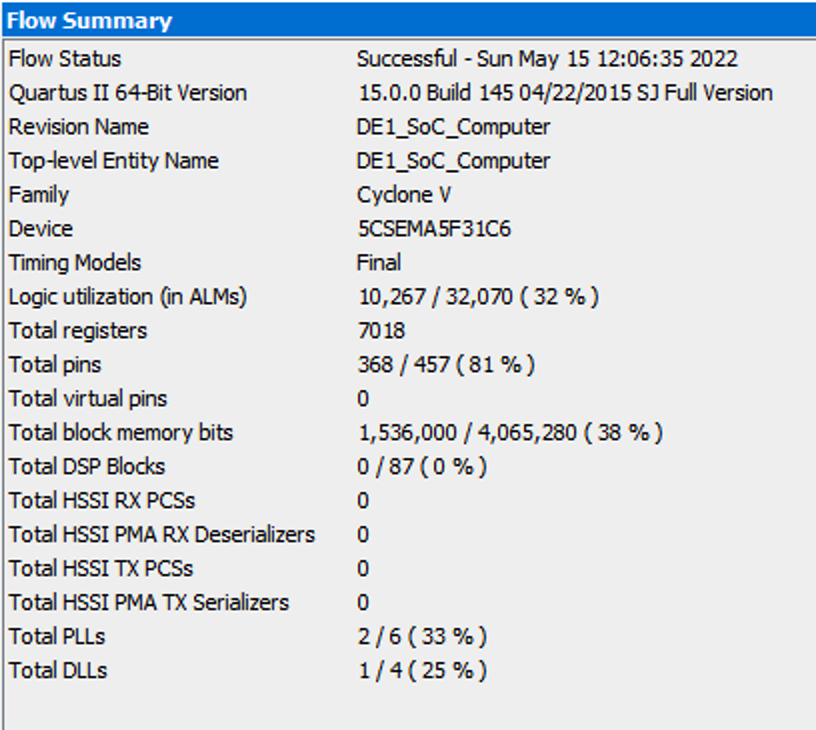
The flow summary report after hardware compilation shows resource utilization on the FPGA for this particular design. The picture below is a screenshot of the summary. Our design uses 32% of logic fabrics, 38% block memory, and 0% DSPs. An naive estimation would show that the resources on board could probably support rendering in 1080p @ 60Hz as well (with slight modifications).
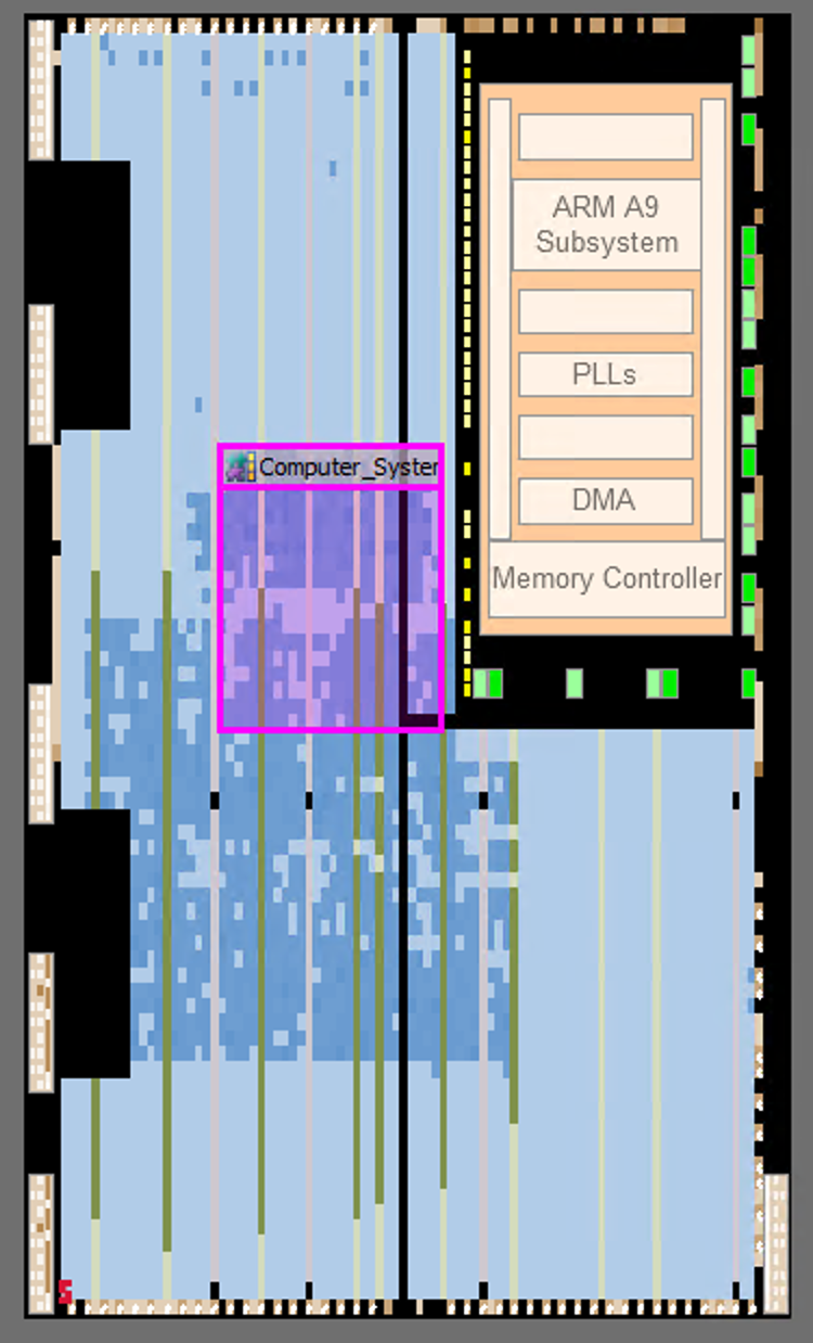
The chip planner diagram below agrees with the flow summary report.
Energy Efficiency
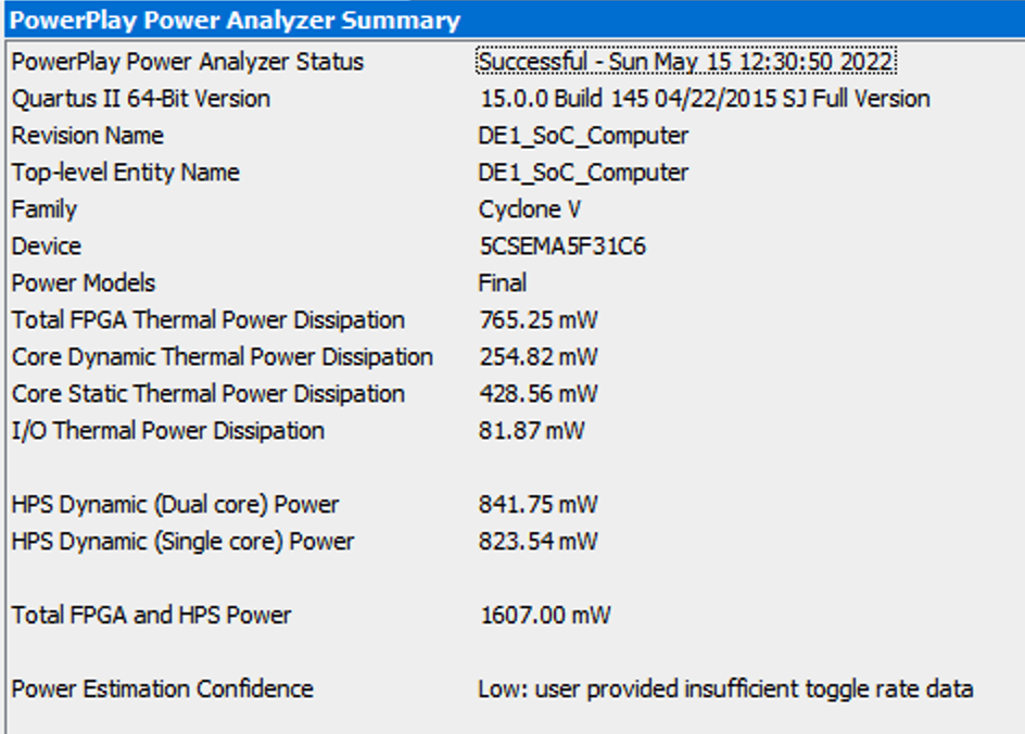
We used Quartus PowerPlay to estimate power consumption of this design. The screenshot below is showing 1.6 W of power consumption for HPS and FPGA combined, with the HPS running at 100 MHz and IO toggle rate at 0.5 transitions/s. This is an aggressive estimation, meaning the actual power consumption will likely be lower.
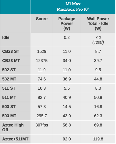
We want to compare energy efficiency between our design and an expensive laptop SoC we have lying around. Analysis from Anandtech (picture below) shows ~10W of power consumption when running single-thread benchmarks. Our design uses 16% of the power while being ~10X faster (speed comparison measured with a C program compiled with -Ofast without graphics rendering). We would like to argue this is an impressive result.
Conclusion
We have built an HPP model simulator on a 640 x 480 screen with each pixel on the screen representing one grid cell. We achieved 60 frames per second of rendering speed with less than 50% of FPGA resource utilization. The design also features user interactions via toggle switches, buttons, and a mouse. We have also demonstrated speed/power advantages compared to a state-of-the-art high-end mobile SoC. All our initial design requirements are met.
If given more time, we will attempt to add the following features into the project:
- Comprehensive software suite for drawing custom bitmaps.
- Automatic resolution and refresh rate detection. This may require a different development board.
- Custom color palette.
- Moving from HPP model to FHP model.
All reused code and design are given credits to in the HW/SW and Appendix section. We also used Altera's Parallel I/O Ports IP, which is distributed as part of the Quartus software.
We do not see any patent/trademark concerns related to this project. Excluding components that are credited to external sources, other portions of the design are fabricated in-house.
This is an open source project through the MIT license.