Logical Structure
The Video-in subsystem in Qsys processes the NTSC video input and the color information of each pixel is written to an on-chip SRAM. We read from this on-chip SRAM and process the pixel color information. Then the processed color information is stored in an M10K block and read by a customized VGA driver to the screen. This high-level logic is shown in the diagram below.

There is only one state in our FSM, which is to update the x and y address to read from the on-chip SRAM for them to cover the video input space. Note that we leave the four edges black by only allowing the VGA space to cover [1, 638] x [1, 478], since there are no results from the Sobel filter convolution at the edge. This state is entered only at a certain time delay to ensure that the pixel information is in the on-chip SRAM.
Custom VGA_driver and Color Representation
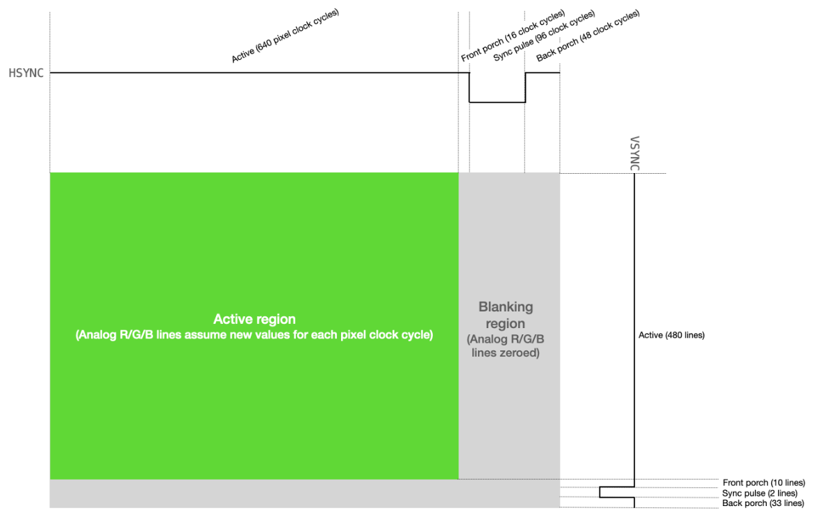
The custom VGA driver is provided on the course website (References 1). This driver supplied the outputs necessary to communicate with the VGA by implementing the standard VGA protocol, illustrated in the figure below. The VGA driver has two outputs, next_x and next_y, which indicate the next pixel address that it will write to in the next cycle. We input the color_in to tell it what color to write to the next pixel.
One problem we encountered was that the VGA driver covers the pixel range of 640x480, but the Video-in subsystem only gives 320x240 pixel inputs. Without processing, the video-in input can only take ¼ of the screen. We solved this problem by right-shifting the next_x and next_y values by 1, which is to divide them by 2, so that the two neighboring pixels are written the same color information, thus doubling the size of the image both horizontally and vertically. A problem that we failed to solve is that although the video input has a dimension of 320x240, it is actually separated into two 320x120 images. The video input is not distorted, but truncated. According to Bruce, this could be determined by the Video_In_Scaler component in the subsystem. There is a width scaling factor and a height scaling factor in this scaler. We still need to dig into the datasheet for the appropriate setting.
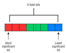
The color information is configured in the 8-bit format, which uses the 3 most significant bits for the value of red, the 3 middle bits for the value of green, and the 2 least significant bits for the value of blue. This configuration gives red the value range of [0, 7], green the value range of [0, 7], and blue the value range of [0, 3].
Qsys Configuration
The video-in-dma-master port of the Video-in subsystem is connected to an on-chip SRAM, so that the input pixel colors are directly stored in this on-chip SRAM module.
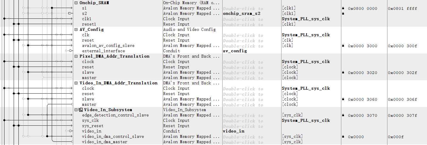
The address configuration of this on-chip SRAM module is in x-y mode, which means that it’s computed by the concatenation of {y, x} added to the on-chip SRAM base address. Although this mode leaves some address space unused, it saves the trouble of multiplication.
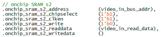
To read from this on-chip SRAM, we started with using the Avalon Bus module from Bruce’s example, but found that the bus limited us to only read and write a single pixel at a time, which is inconvenient regarding our intended whole-image processing. After consulting Professor Adams, we decided to expose a slave port in the on-chip SRAM module, so we can directly read out the pixel color information video_in_read_data from the top module Computer_System.