Grayscale Filter
The algorithm for the grayscale filter is to extract the red, green, and blue information of a pixel respectively, average them, and reassign this average value to the red, green, and blue ranges. We performed right-shifting and masking to the original 8-bit number to extract the values of each color - right-shifting 5 bits for red, right-shifting 2 bits and then masking with 0b111 for green, and masking with 0b11 for blue. After averaging the values, we left shift this number with the appropriate amount for each color (5 for red and 2 for green) and perform the OR operator to combine them into one 8-bit color representation.
Sobel Filter Math Background and Implementation
The Sobel operator uses two 3×3 kernels to convolve with the original image to calculate approximations of the derivatives – Gx for horizontal changes, and Gy for vertical.
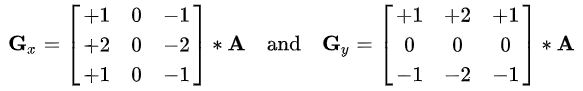
After convolution, we compute the final sobel outcome by sqrt(Gx^2+Gy^2) or |Gx|+|Gy|. We chose the later formula since square root is difficult to manipulate in Verilog, and it’s not necessary to compute the angle between Gx and Gy in our project.
From the above formula, we decided that we need 8 inputs to the Sobel filter module - 8 pixel color information except for the middle one, since the middle pixel is always convoluted with 0. Inside the Sobel filter module, the convolutions with Gx and Gy are performed using shifts and adds. The absolute values of Gx and Gy are determined by two muxes. This results in one 8-bit final value, which is then shifted and masked to be distributed in the slots for red, green and blue as described in the Grayscale filter session above.
Entire Image Computation Implementation
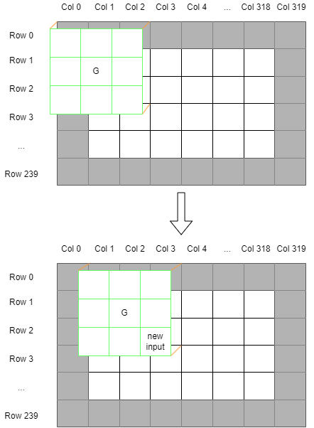
To feed the correct 8 pixels into the sobel filter module at real time, we designed an image compute module to generate input for the sobel filter module. Since the sobel filter requires a 3x3 matrix input to perform convolution and the middle one is not needed, the image_compute module prepares the 8 inputs. The input pattern requires certain modifications before passing into the sobel filter. As shown in the row-major order figure below, it reads one pixel at a time from the on-chip SRAM in row-major order, which means that the first 3x3 input matrix will not be ready until pixel in Row 2, Column 2 is ready. It indicates that the top row, bottom row, left column, and right column will all be discarded in the soble convolution or we have to figure out a way to fill in pixel data for the edge cases. We decided to abandon the edge because we realized that one pixel will not be apparent to human eyes and will not significantly affect our design. The 3x3 matrix and row-major order also indicate that this requires 643 inputs to be read in first before the first convolution happens. We realized that it causes a tremendous amount of overhead each frame and it is best that we store the pixels somewhere since it will be used for later calculations. So we decided to use a large register to act as a buffer that can store the three rows of pixels. The buffer stores all three rows, so we are preparing for sobel filter inputs, we have all pixels from storage and just require the lower right corner pixel to fill in the gap. This means that the convolution can begin after 643 iterations of writing to the buffer. The buffer will continue to be filled up in parallel with sobel convolution.
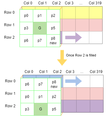
As shown in the row buffer figure below, after Row 2 is filled, we will move the index for new input to be 0 so that it can start filling out Row 0, which replaces the oldest pixel information. In this case we obtain a First In First Out pattern for the row buffer and only need to update one pixel everytime a new pixel comes in. This way, we only need to change the index to read from the buffer to get different input pixel for sobel filter. It it shown in the lower figure that the output G is on the bottom row, since Row 0 is the row with the newest input, the input matrix simply wraps around. After Row 0 is filled, we set the index to be at the beginning of Row 1 which contains the oldest pixel information and input matrix wraps around again to adjust to the change. We repeat the similar pattern until the whole picture has been calculated except for the edge row and column.
FSM for Sobel
Now we have know our target, we designed a FSM for it. INIT and WR states are designed to fill the row buffer till Row 2, Column 1. We can see that there are three PRE states and three CAL states, each representing a type of pattern for the input matrix index. For example, PRE0 and CAL0 represents the pattern shown in the upper image in Figure y. After WR we have enter a PRE0 state, which is used to account for the middle pixel -- we need to read and store this pixel in row buffer but should not be in the calculation state since the input matrix for sobel filter is not ready yet. Then it directly enters CAL0 state. All CAL states are designed to prepare the 8 inputs, update the row buffer, increment row buffer index, set write enable high for M10K block, increment write address for M10K block all at the same time. It stays in the CAL0 state until Row 2 is filled. Then as all the other CAL states, CAL0 state goes directly to UPDT state. In UPDT, there is a counter to keep track of the order of CAL states and ensures that the index are set up correctly. UPDT state also reads in the first pixel input for the desired row depending on which PRE state it is going next. UPDT state acts as a router that follows round-robin pattern, assigning different indexes and moving to different PRE states. It goes back to INIT once all rows are done.
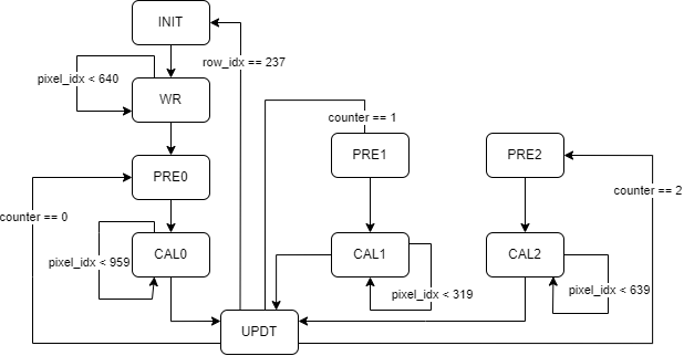
There is also another important feature we added to ensure correctness -- the valid interface. Since we write to the row buffer in all the states and increment M10K write address in some of them, we need to be careful and only allow those update when a new input is passed in. Since we are not certain the amount of cycles it takes to read from op-chip SRAM, we added a valid signal and only set it to be high when an input is ready. We then add an if statement to all the states so that they only update while valid is high. In this case we can ensure that every time there is an update, we have a new input.