Testing
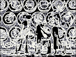
Debugging was challenging for this project because all our inputs and outputs are connected to the FPGA. We struggled to find a good way to debug and spent quite a bit of time. To ensure that we correctly produce the sobel edge image when the input pixels are fed in one-by-one, we 1. compared the Modelsim output with a Python sobel algorithm output and 2. Used a Python script to generate an image using the exported Modelsim data list, so that we can directly see the edge effect. First we needed to preprocess an image to mimic the video input from the NTSC camera. We downloaded a random picture (actually not random! It is from Muse Dash - a fantastic music game that we loved!) in png format (Figure a). Since this image is in RBG format (three 8-bit numbers for each pixel - 1 for red, green, and blue respectively), we first used Python to transform it into the 8-bit representation that we use (Figure b). Although we lost some color information - as you can see some gradient effects become not as smooth - it is still bearable. Then we changed its dimensions from 1920x1080 to 320x240 (Figure c). Now it becomes really blurry…but is still recognizable. Then we feed it into a Python grayscale converter and produce Figure d, but in a txt file which contains all the pixel values in order. Then we fed this txt file to both Python and Modelsim. After a few attempts, we found that the pixel-to-pixel comparison between Modelsim and Python didn’t work well because there are simply too many pixels. So we only compared for a rough pattern to ensure that our Modelsim result was not a total mess. After Modelsim displayed some pattern, we wrote another Python script to directly generate an image from the exported list of the pixel information in Modelsim, so that we can observe if it has the proper edge effect or not. We also wrote a Python Sobel algorithm to generate an edge image, so that we gained intuition about what the correct edge effect looks like.