Youtube video of catcher in action.
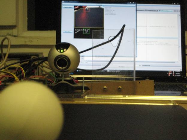
Image showing the view looking at the ball catcher and the PC. If you look closely you can see the PC outline where the ball is in the camera view.
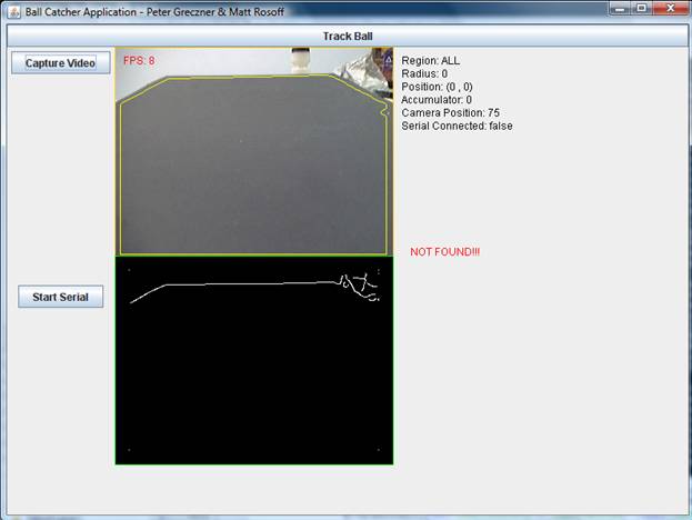
This is the main image of our GUI. It shows the status of a few important facts. Right now it is processing on the entire image (Region = ALL). The serial communication is not connected, and the ball has not been found. The Camera Position is the position at which we will set the camera when we establish serial communication. In our setup, 75 means center. Also notice the yellow polygon that outlines what our algorithm believes to be the black sheet.
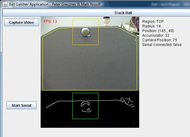
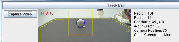
This image shows what the processing looks like when we have found a ball. There are a few interesting things to notice in this new image. First see how the region specified is now TOP. This shows that we have found the ball in the TOP region and for now, that is the only region worth processing on. Also, the green and yellow squares indicate what region we are performing our CHT on. The blue circle, is indicating where the CHT has determined the ball is and with what radius. This information is also printed on the right hand side of the window. One important thing to also notice, is that the FPS has now risen to 13 per second. This is due to our optimization of the region for the Canny edge detection and for the CHT.
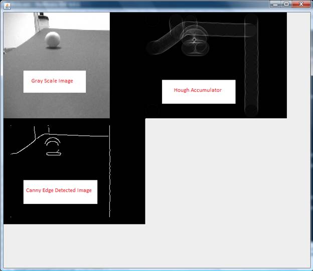
Image showing the gray scale input, the edge image, and the Hough Accumulator. Notice on the Hough accumulator the center region where the concentration of pixels is much higher than in other regions. This indicates that we are most likely looking at a circle of the inputted radius.
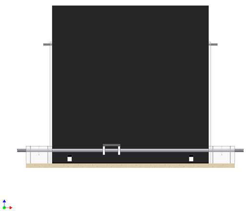
Depicted is a rear image of the mechanical setup.
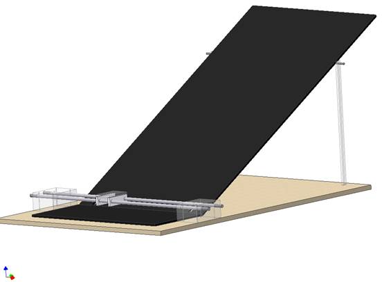
Depicted is an isometric view of the mechanical setup, seen from the front.
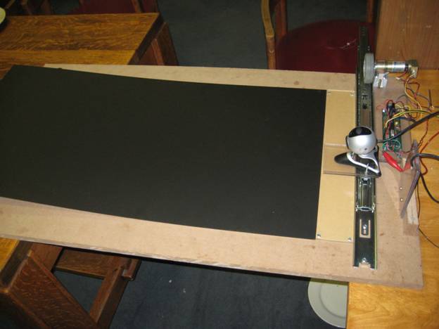
Image of the full ramp.
|