Hardware Design
PGC-32 is based on PIC32 as the microncontroller and integrated with multiple peripherals that allow the interaction of the user with the system. Grouping the components in terms of direction that data is flowing, there is a joystick, accelerometer and push buttons as input components while a TFT screen, speaker and vibration motors as output components. The whole system is powered by 6 V generated by 4 AAA batteries in series. The PIC32 functions at 3.3 V so there is a linear regulator that lowers the voltage from 6 V to 3.3 V. The only device directly connected to 6 V is the vibration motors.
TFT Display
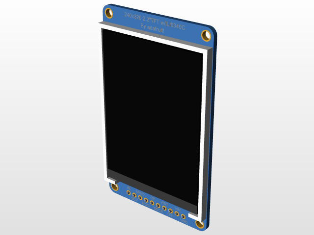
2.2" 18-bit color TFT LCD display with microSD card breakout. This device uses a 4-wire SPI to communicate with the microcontroller. To access the microSD, we can also use the same communication protocol. The size of the screen is 240 x 320 pixels and can display full 18-bit color (262,144 shades). It is used in our system as the main output component where the user can see the state of the game. It operates at 3.3 V.
Joystick
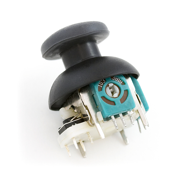
2-Axis Joystick. It is mainly composed by two 10K potentiometers in both x and y direction. It also includes a push button. Breakout will be Vdd (3.3V), GND, X value, Y value, and Push button. In our system, it constitutes one of the main action components that allows the user to interact in the game. The X and Y values are connected to ADC ports in the PIC32. Since our microncontroller has 10-bit ADC, the maximum possible reading is 1024,so the initial value (rest position) of the Joystick will read around 520.
The joystick in particular was a complicated component in terms of interfacing with other systems. The footprint for it is very specific, so we used the pcb design by Adafruit as reference. In the same way, the joystick is one of the elements that interfaces with the top part of the case and marks a height that no other component has; therefore, it was very challenging to come up with the exact design for it taking in consideration the difference in height in comparison to the rest of the components.
Accelerometer
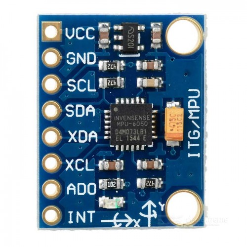
MPU6050. This is a 6-axis accelerometer/gyro that communicates data via I2C. We use it as main component of interaction of the user with the game, which converts the PGC32 in a tilting device. We only make use of the accelerometer readings from X and Y axes to move the plane in the game. Because the readings from this device are noisy, we need to use a software average filter for the data.
Vibration Motors
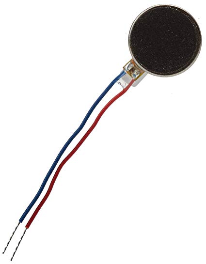
Vibrating Mini Motor Disc. These consists of vibe motors completely sealed up and easy to embed by the use of sticker. We use it in our system in order to make the game more interactive so the user cannot only watch and listen to the effects of the game but also feel them through difficult situations in the game. The motors are connected to 6 V and the circuit is closed by control of the base of an NPN transistor. The control is made by a digital pin that generates the PWM signal and has a 1K resistor in series.
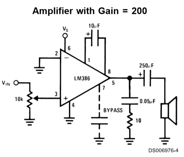
Audio Analog Circuit
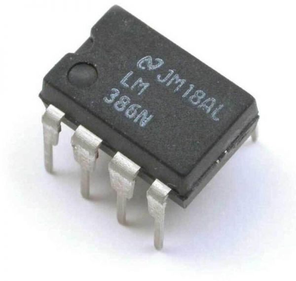
Low Voltage Audio Power Amplifier. It contains a wide supply voltage range of 4V-12V or 5V-18V and low quiescent current drain of 4 mA. It has a bandwidth of 300 kHz and voltage gains from 20 to 200 depending on the configuration of the circuit. The package we use in the project is 8-pin DIP, which facilitates its replacement. The circuit developed is to obtain the maximum gain of 200.
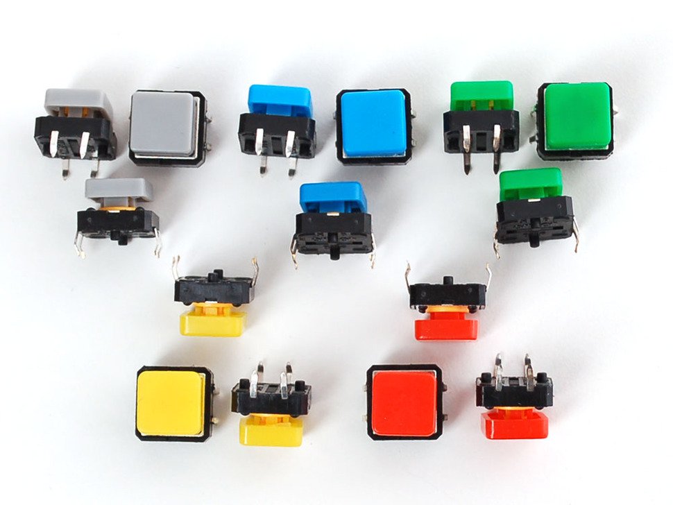
Colorful Square Tactile Buttons. These buttons are used as main action components for the user to interact in the game. Essentially, the circuit for each button consists of a voltage divider configuration where the button acts as a low-side switch, having a 10 K pull-up resistor connected to Vdd (3.3V). To improve accuracy, the buttons are properly debounced using a Finite State Machine described in the Software section.