Software Design
The software component of this project is divided into main portions: graphics displayed on the TFT and the gameplay itself which lets the user enjoy a fair and defying game. In the next sub-sections we will explain every detail behind the making of the software that composes this project. We will mainly focus on how the design interacts with the input peripherals that are installed in the PGC-32 and how the system controls the output peripherals as well.
Configuration
This sub-section explains how we set up the different peripherals and internal features from the PIC32 microcontroller that let us develop this game. The majority of such configuration commands are placed in the main.c file before we let the scheduler execute any of the available threads.
Configuration of Timer3 and DMA:
In our game we produce sounds through the speaker by using Direct-Memory-Access (DMA), which uses memory controllers separate
from the CPU to accelerate data movment between memory locations, or between peripherials and memory. This enables us to allocate or
CPU power for the game graphics and processing.
OpenTimer2(T2_ON | T2_SOURCE_INT | T2_PS_1_1, timer_limit);

                            DmaChnOpen(dmaChn, 0, DMA_OPEN_AUTO);

                            DmaChnSetTxfer(dmaChn, sine_table, (void*)&SPI2BUF, sine_table_size, 2, 2);

                            DmaChnSetEventControl(dmaChn, DMA_EV_START_IRQ(_TIMER_2_IRQ));
The program uses the Interrupt Service Routine (ISR) for Timer2 to enable and disable the ADC channel. For sounds, we created a sine table of
256 elements with values of up to 4095, which is the maximum executable value you can send to the DAC channel. Then if we want to syntethize a
specific frequency, we just set up the right value for timer_limit such that you obtain the following equation:
Fout = timer_limit * SYS_FREQ / 232
SPI Channel Configuration:
For our program, we mainly enable SPI because it facilitates the communication between the PIC32 microcontroller and the TFT screen. The following
block of code enables such feature:
SpiChnOpen(SPI_CHANNEL2, SPI_OPEN_ON | SPI_OPEN_MODE16 | SPI_OPEN_MSTEN | SPI_OPEN_CKE_REV | SPICON_FRMEN | SPICON_FRMPOL, 2);

                            PPSOutput(2, RPB5, SDO2); // SDO2 (MOSI) is in PPS output group 2

                            PPSOutput(4, RPB10, SS2);
Timer3 and Output Compare for PWM:
Since we were using Timer2's IRQ for producing DMA sounds, we decided to configure Timer3 solely for the purpose of implementing the functionality
of the vibration motors.
OpenTimer3(T3_ON | T3_SOURCE_INT | T3_PS_1_1, generate_period);

                            ConfigIntTimer3(T3_INT_ON | T3_INT_PRIOR_2);

                            mT2ClearIntFlag();

                            OpenOC3(OC_ON | OC_TIMER3_SRC | OC_PWM_FAULT_PIN_DISABLE , vibmotor_pwm, vibmotor_pwm);

                            PPSOutput(4, RPA3, OC3);
The value that generates the square PWM signal is actually the signal from the output comparator, that essentially just compares the current value
that drives the vibration motors with vibmotor_pwm . By using the command SetDCOC3PWM(pwm_on_time) we can variate the PWM
signal entering the motor and therefore decrease/increase its vibrations.
Pushbuttons and Button Switches:
In the system we have three registered digital inputs. Their declarations are shown below:
/* ========= Setting input pin for pushbutton1 ========== */

                            mPORTASetPinsDigitalIn(BIT_4);


                            /* ========= Setting input pin for pushbutton2 ========== */

                            mPORTASetPinsDigitalIn(BIT_2);


                            /* ========= Setting input pin for game switch ========== */

                            mPORTBSetPinsDigitalIn(BIT_4);
This simple code enables us to receive digital input from these buttons. Refer to the hardware section for the
pushbuttons in order to see how the set-up circuit was implemented.
I2C Setup:
For this project we relied heavily on I2C to implement the communication with MPU6050 accelerometer. The configuration settings consist of
two important steps:
OpenI2C1(I2C_ON, 48); // open I2C communication

                                char data[] = {0};

                                i2c_write(0x6b, data, 1); // Take the MPU 6050 out of sleep mode
The piece of code essentially opens up the I2C channel for communication and takes the accelerometer board out of sleep by writing a single
byte (0x0) to the 0x6b address that corresponds to the slave address.
Configuration of ADC Channel:
For this project we relied heavily on I2C to implement the communication with MPU6050 accelerometer. The configuration settings consist of
two important steps:
 CloseADC10(); // ensure the ADC is off before setting the configuration

                                #define PARAM1  ADC_FORMAT_INTG16 | ADC_CLK_AUTO | ADC_AUTO_SAMPLING_ON

                                #define PARAM2  ADC_VREF_AVDD_AVSS | ADC_OFFSET_CAL_DISABLE | ADC_SCAN_OFF | ADC_SAMPLES_PER_INT_2 | ADC_ALT_BUF_OFF | ADC_ALT_INPUT_ON

                                #define PARAM3 ADC_CONV_CLK_PB | ADC_SAMPLE_TIME_15 | ADC_CONV_CLK_Tcy

                                #define PARAM4 ENABLE_AN5_ANA | ENABLE_AN11_ANA

                                #define PARAM5 SKIP_SCAN_ALL


                                /* ======== Configure ADC to sample AN5 and AN11 on MUX A and B ========= */

                                SetChanADC10( ADC_CH0_NEG_SAMPLEA_NVREF | ADC_CH0_POS_SAMPLEA_AN5 | ADC_CH0_NEG_SAMPLEB_NVREF | ADC_CH0_POS_SAMPLEB_AN11 );

                                OpenADC10( PARAM1, PARAM2, PARAM3, PARAM4, PARAM5 );

                                EnableADC10();
The piece of code above initializes ADC10 with channels 0 and 1. These two channels correspond to AN5 and AN11 respecitvely, which are connected to
the potentiometers in both axis of the joystick.
Initialization of Threads:
Below we are initializing all the threads that compose this system. In the next section we will explore the functionality of each of these threads,
how they integrate with the system's internal and external peripherals and how they essentially build the game.
PT_INIT(&pt_joystick);

                                PT_INIT(&pt_button1);

                                PT_INIT(&pt_button2);

                                PT_INIT(&pt_accel);

                                PT_INIT(&pt_dma_sound);

                                PT_INIT(&pt_pregame);

                                PT_INIT(&pt_game);

                                PT_INIT(&pt_postgame);

                                PT_INIT(&pt_timer);
Gameplay
Joystick Thread
Since we are not using the pushbutton of the joystick on this project, the thread only deals with converting the readings from both
axis through the ADC channels into positions of the plane inside the field. Given how sensitive the joystick is, we implemented a circular buffer
with 8 elements so that could a running average on the horizontal movement of the plane. We chose 8 so that we could shift left by 3 (1 cycle)
instead of divide by 8 which can take multiple cycles (~50):
joy_x = ReadADC10(1);

                            joy_y = ReadADC10(0);


                            raw_gun_x = ((193 * joy_x) >> 10) + 101;

                            xPos_avg[avg_idx] = raw_gun_x;

                            avg_idx = (avg_idx+1 == 8) ? 0 : avg_idx+1;

                            gun_x = running_avg();


                            obj_speed = ((2 * joy_y) >> 10) + 1;
The code above sets the variables gun_x and obj_speed as the customized readings that the plane should take into consideration
when moving in both axis. Both of these variables are global and we will explain later how we can use the same variables for the accelerometer
thread and it won't cause an issue.
Pushbuttons Threads
Both pushbuttons threads contain a debouncing state machine that helps us stabilize every button push the user has to make. They set their respective
global variable (button1 and button2) and also enable the DMA channel by writing a period for the timer (which determines the)
frequency of the sound) and also a flag which is used in the DMA thread to enable the selected frequency to be sent to the DAC. Below is the FSM
that implements debouncing:
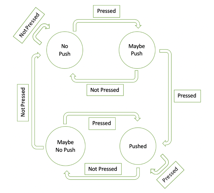
This state machine has proven to be very effective and throughout the course of this class we have implemented it for every lab assignment that
interacts with pushbuttons.
Accelerometer Thread
The accelerometer thread is very similar to the joystick thread in which it only reads from the MPU 6050 and converts the values from the x and y axis
to relative plane positions using the same conversion method as the joystick thread. Here is code that achieves this:
readImuValues(i2c_reads);


                            raw_gun_x = ((193 * (int)(i2c_reads[1] + 16000)) >> 15) + 101;

                            xPos_avg[avg_idx] = raw_gun_x;

                            avg_idx = (avg_idx+1 == 8) ? 0 : avg_idx+1;

                            gun_x = running_avg();


                            obj_speed = ((2 * (int)(i2c_reads[0] + 16000)) >> 15) + 1;
The function readImuValues() is a function provided by the library
i2c_helper.h provided by one of the past groups which also took this class. This function basically handles all the protocols for initiating transactions
and essentially outputs the readings from both the accelerometer and the gyroscope, which are stored in the i2c_reads array to be used further down.
Since the accelerometer readings go from approximately -16,000 to 16,000 (at least in our case), we offset the value read from the MPU by 16,000 and then
convert it as addressed before. Like we discussed before, we are using the same global variables to store the raw and adapted values for the x and y
positions assigned to the plane. In the Thread Scheduling sub-section it is explained how this is achieved and why it does not cause any issues.
DMA Sound Thread
The code for the DMA thread is plain simple and it is shown below:
PT_YIELD_UNTIL(pt, sound_flag);

                            sound_flag = 0;

                            DmaChnEnable(dmaChn);

                            PT_YIELD_UNTIL(pt, ((!button1 && !button2 && !pre_game_count) || post_game));

                            DmaChnDisable(dmaChn);
We first yield from this thread until the sound_flag variable is set (as explianed in the pushbuttons thread). Then it clears the flag,
enables the DMA channel that uses the period set by the pushbuttons threads to output a frequency sound to the DAC, and then waits for a couple of
conditions which refer to different scenarios. The first one is releasing the pushbuttons while still playing the game. This basically means that
as long as the user plays any of the two pushbuttons while playing, it will output a specific sound depending on the button pressed. The other
condition is that if the program enter the post-game thread (explained below), we also stop the sound. This was included to improve performance rather
than functionality.
Pre-Game Thread
This pre-game thread is purely based on graphics and only a couple of features that pertain to the gameplay (see the Graphics section below for
more info on this pre-game portion). The most important feature of this thread is the reset of significant signals
to be used in the gameplay thread. Such signals are shown below:
pre_game = 0;

                            restart_game = 1;

                            num_bullets = bullets;

                            destroyer = 0;

                            initBricks();
The block of code above indicates that the system is transitioning out of the pre-game scenario, that the game is being restarted, it refills the
player with the default amount of bullets (50), disables the destroyer, and initializes all the bricks in the game to invalid and waiting to be
placed inside the game.
Gameplay Thread
This is the biggest thread in the program and it is the one that implements the gameplay. The first thing it does is that it checks if the time remaining is 0. If this is the case, it means the user won the game and the program transitions to the post-game thread explained below. If there is still time remaining, it proceeds to executing all the processing for the game. It starts with drawing the green laser if it detects that button1 (blue) is pressed. As explained in the Graphics section, the program calls the DetectHit() function to see if the plane hit a target. If it did, then it checks if it is bricks; if that is the case, then it compares the amount of bullets from the plane and the weight of the brick:
- If the plane has more bullets, then the bricks is destroyed and the plane is left with the remaining bullets
- If the plane has less bullets, then the bricks stays with the remaining weight and the plane shows a red 0 under the bullets part and cannot shoot anymore until it recovers more bullets.
Post-Game Thread
Similar to the pre-game thread, this thread is purely based on graphics and more inforamtion can be found in the Graphics section below. At a high- level, it detects whether the user won or lost the game an displays the appropriate message on the screen. Then, it proceeds to transitioning to the pre-game thread again to start a new game.
Timer Thread
This thread decreases the global variable play_time after yielding for exactly 1,000 msecs (1 second). We use this thread as our internal clock which is displayed on the playing screen at all times.
Timer3 ISR
This Interrupt-Service-Routine (ISR) for Timer3 corresponds to the portion of code that enables the PWM for the vibration motors. The small piece of code is shown below:
mT3ClearIntFlag();
if(!post_game && ((button1 && (num_bullets > 0)) || (button2) || pre_game_count)){
SetDCOC3PWM(vibmotor_pwm);
}
else{
SetDCOC3PWM(0);
}
The code above implies that the motors will vibrate only under certain conditions: when we are currently playing a game and the player presses a button and still has bullets remaining; if the player presses the destroyer button; or at the countdown sequence at the beggining of the game. At all other scenarios, the vibration motors are not enabled.
Thread Scheduling
For thread scheduling, we thought it was appropriate to create a selection method that only executes certain threads depending on the status of the game. The table below contains all selection parameters and all instances of the game:
| Threads | Pre-Game | Game | Post-Game |
|---|---|---|---|
| Joystick | X | X if game_mode is joystick |
|
| Button 1 | X | X | |
| Button 2 | X | X | |
| Accelerometer | X if game_mode is tilting |
||
| DMA Sound | X | X | |
| Pre-Game | X | ||
| Game | X | ||
| Post-Game | X | ||
| Timer | X | X | X |
A very important piece of information that we have discussed previously is how the joystick and accelerometer threads use the same variables to read from the sensors and control the airplane. Now we know why it does not cause an issue: it is because depending on the current vaue of the swtich (game_mode), we schedule the correspondin thread and ignore the other one. A similar scenario occurs with the pre-game, game, and post-game threads, where graphics and functionality don't overlap because only one of them is scheduled at a time.
Graphics
The graphics on this project were made using the functions provided by Professor Bruce Land in the graphics libraries tft_gfx.h and tft_master.h . Such libraries were of great help generating common figures and patterns that got to be displayed on the 2"2 TFT screen provided by the course staff. It is important to point out that since the game thread is yielding every 30 msec, the game has a frame rate of 33 f/s. Now let's quickly go over how the most important screen scenarios throughout the game are developed.
Welcoming Screen:
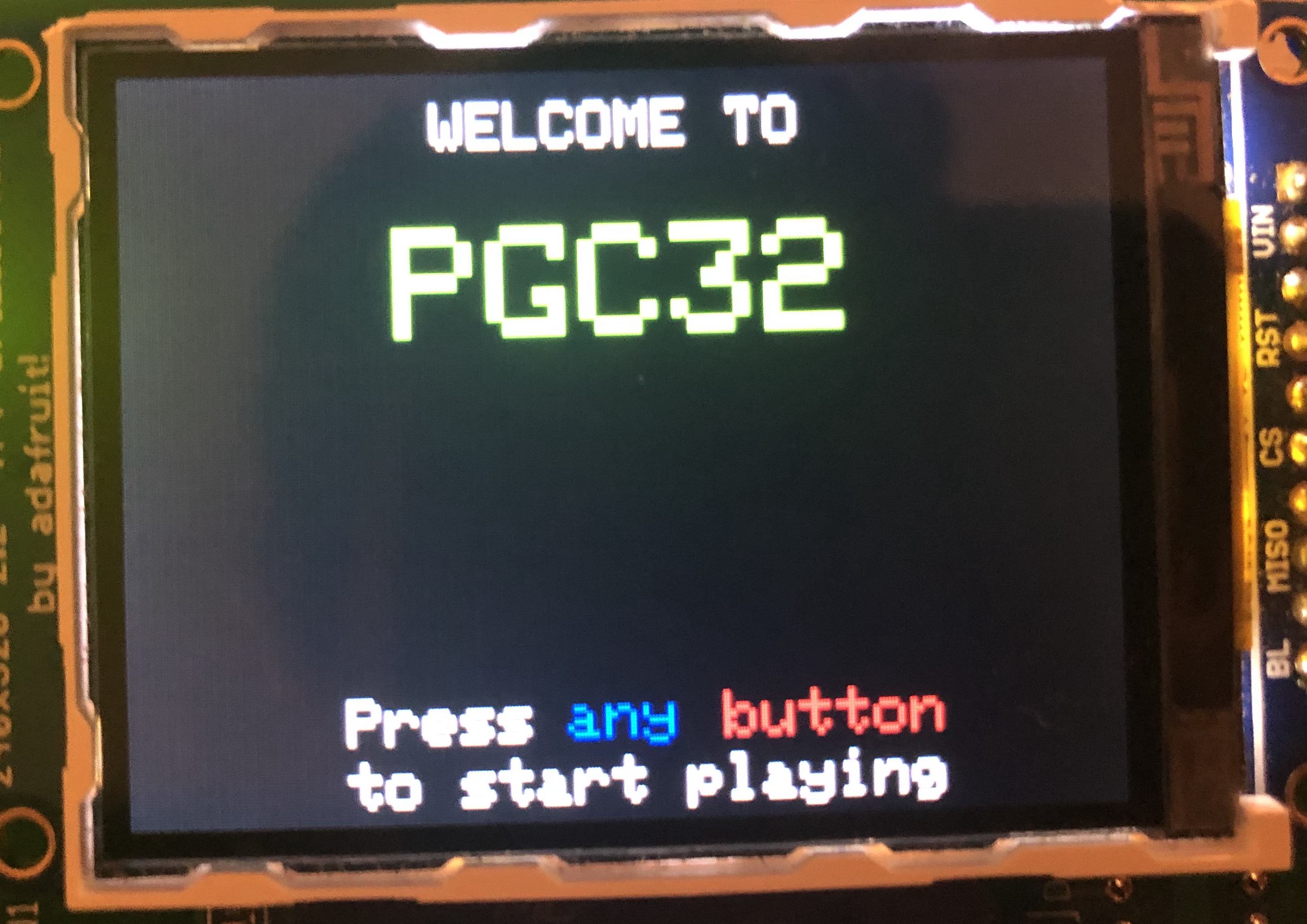
This is the first window the user sees when he/she starts playing the game. It welcomes the user to the portable-console and indicates that to
start a new game, he/she only needs to press any of the two buttons. The main usage of library functions in this case is structured as follows:
tft_setTextColor(ILI9340_WHITE);
tft_setTextSize(2);
sprintf(buffer, "WELCOME TO");
tft_writeString(buffer);
Everything that required outputting characters to the TFT screen was made using similar pieces of code. In this case, we write specific words
to a buffer variable that can contain up to 80 characters and then use tft_writeString to print on the TFT.
Choosing a Difficulty:
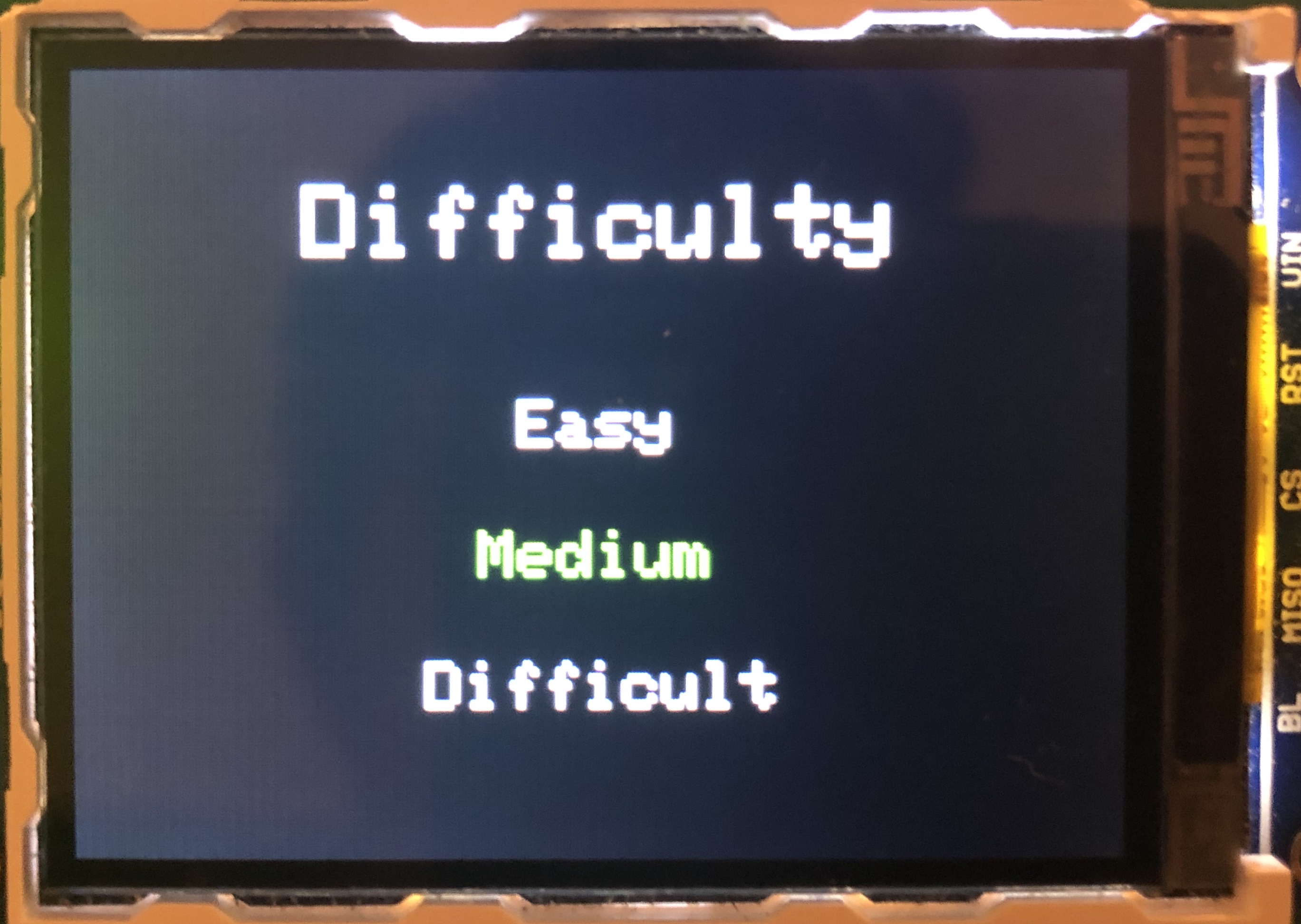
After the player agrees to start a new game, the program lets the user pick a difficulty. The game supports up to three levels: easy , medium , and difficult. As it can be seen on the screen, the currently selected level of difficulty is medium as it is highlighted in green. By using the joystick, the user can select the desired mode and it will be appropriately highlighted.
Countdown Sequence:
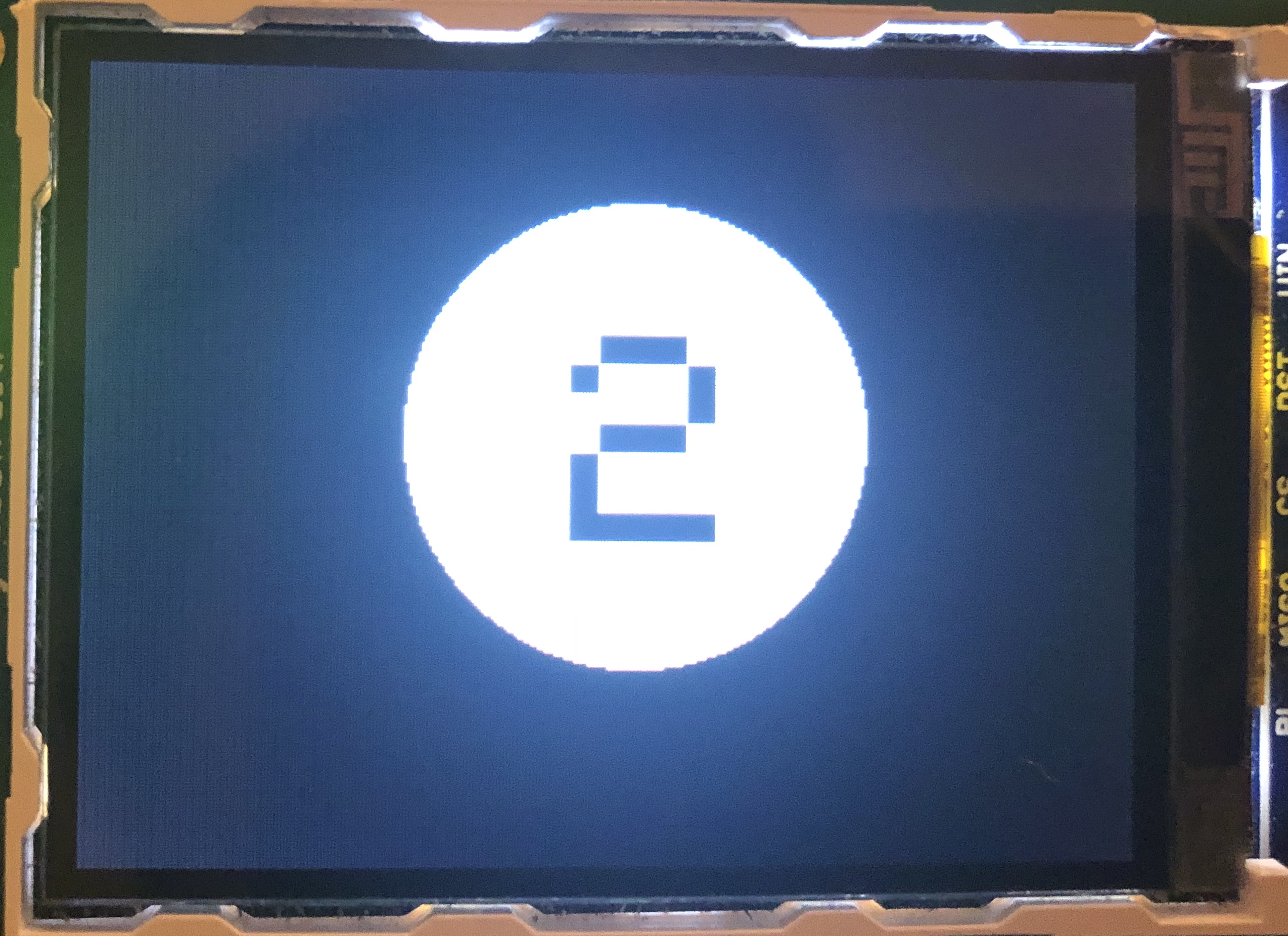
This countdown feature was included because we felt the user may need some time to prepare after selecting a playing mode. It basically counts down
from 3 along with producing a sound and also activating the vibration motors. To achieve this pleasant design, we made use of the following function:
The code above draws a circle at point (165, 110) with radius 70 and in color white. Then it draws the number "2" in size 9 at the beggining of that
circle.
Main Screen:
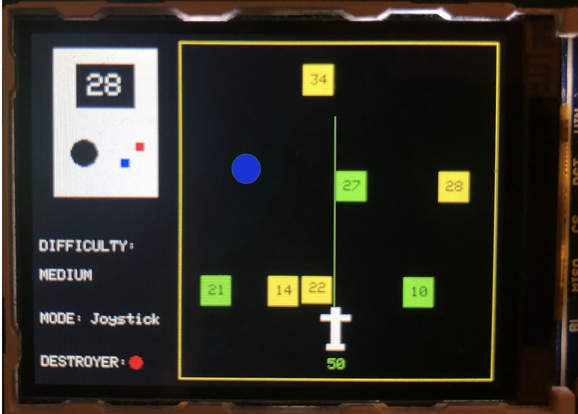
This is the main screen that starts developing when the user begins playing. It is divided into two main parts: the status of the game (left) and
the game itself (right). Let's start with the statys of the game sub-window. What we see at the top is a replica of the PGC-32 that was drawn using
rectangles and circles. The function used to fill rectangles is shown below:
Inside the small black square on the PGC-32 replica is the time remaining for the game to end. It is relatively large compared to the elements of the
screen so that the user can easily and quickly distinguish what it says. Below that, we have the written status for the game: difficulty ,
mode , and destroyer . The last two change in real time as the user interacts with the game. If the player picks up the destroyer ball
(explained in gameplay), the circle next to "destroyer" automatically changes to green. If the player switches playing modes from "joystick" to
"tilting" (accelerometer), then it is immediately updated in the status board.
To the right, we have the actual game. It is composed by five main parts: the yellow bricks that can destroy the plane; the green bricks that can
give the plane more bullets; the blue circle which when caught by the plane, the destroyer power becomes available; the plane itself which is drawn
purely out of white rectangles; and finally the green laser which is used by the plane to destroy the bricks. To move the plane and let the circles
fall, there was no other solution than to erase them and draw the new ones in their respective new position. However, for the bricks and bullet
providers, we performed an optimization technique. Instead of erasing and redrawing them, we realized that since they are not changing in the x-axis
(only y-axis), we could only erase the top part by the distance they are falling and draw the same amount in the bottom. For the weights, we just needed
to draw the same number in yellow (erasing it), move the bricks down, and drawing the same number in black, creating the effect of a consistent fall.
Finally, for the green laser, we call a function detectHit() that returns the position of the hit bricks (if it hit it) or a fixed value if there
was no hit at all. Then, we draw the laser from the top of the plane to the returned number.
Winning Screen:
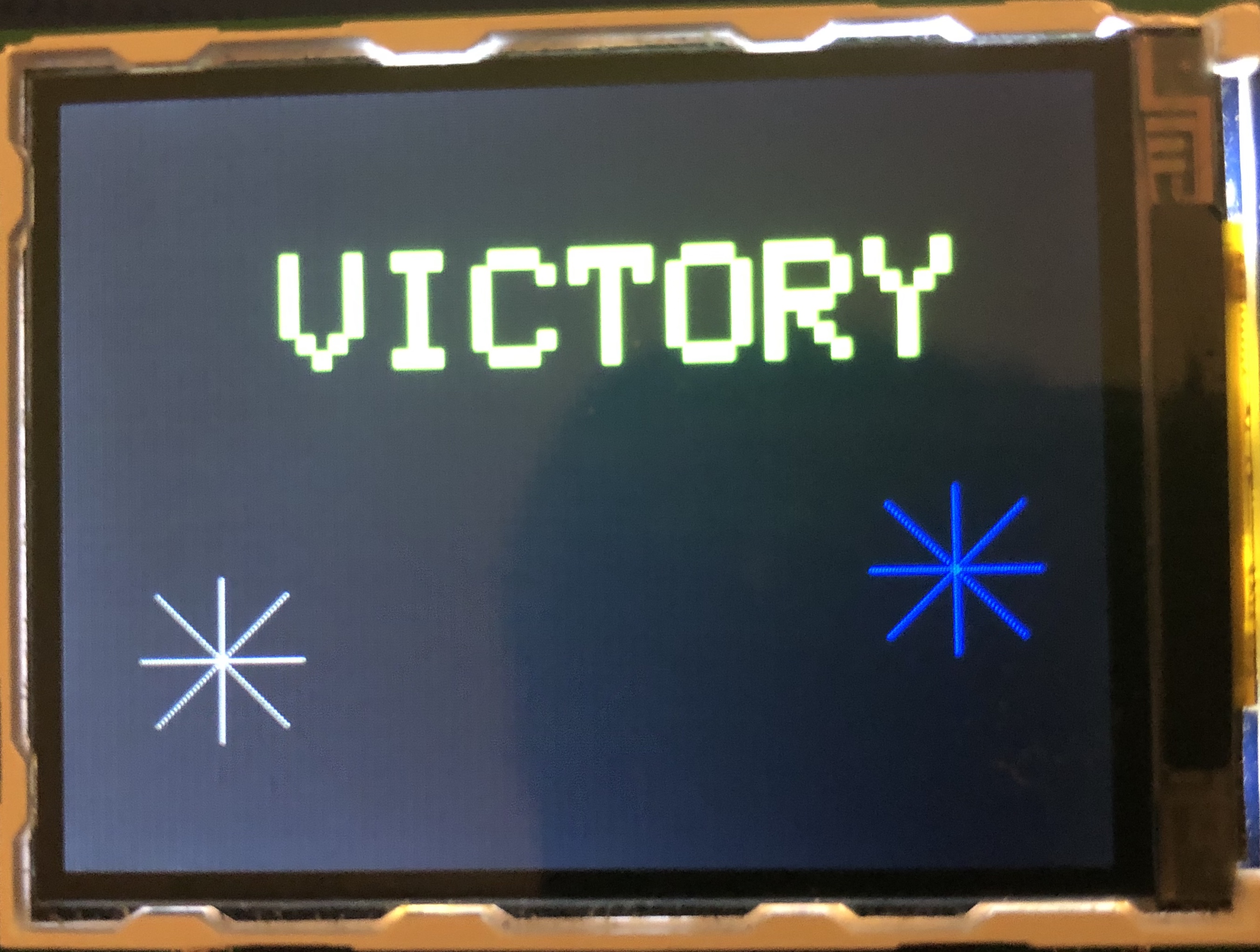
If you see this screen, congratulations! It means you defeated all those bricks that were trying to take you down. To reward the player after a well-deserved win, the system throws a huge VICTORY message along with some interactive fireworks that can be seen better in the demos from below.
Losing Screen:
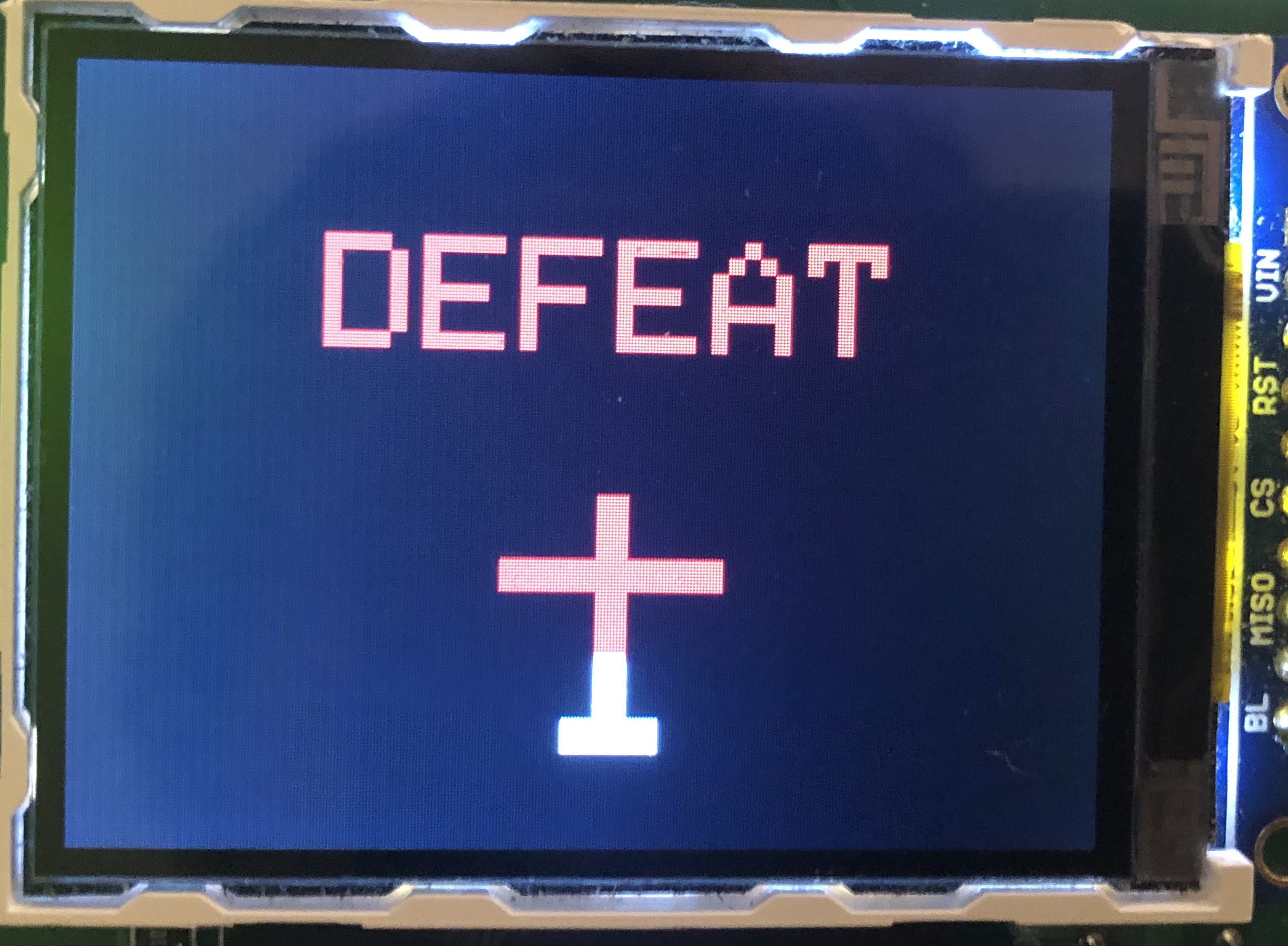
Uh oh ... if the user sees this screen it means a brick destroyed the plane. A whole two-seconds are waited after the player loses when the screen freezes and lets the player know it is not rigged like those other games out there. After that, the system throws a huge DEFEAT message along with some interactive "reddening" of the plane (symbolizes blood or destruction) that can be seen better in the demos from below.