High-Level Design
PGC-32 consists of a handheld game console with two main playing modes: using the joystick or as a tilting device moving it back and forth to produce a movement effect. This offers gamers the possibility to experiment completely different game experiences where they can use the joystick to resolve problematic situations and the tilting mode to spice up easier scenarios. The device includes a 320-by-280 TFT color display, speaker and vibration motors as output devices while the game can interact in the game by using two action buttons, the joystick and the effects of the accelerometer (which gives the possibility of tilting mode). The game developed for the PGC32 is inspired after Snake vs Blocks . The system is powered by 4 AAA batteries.
The development of PGC-32 involves the custom design of its printed circuit board, 3d-printed case and programming of the game which makes it a very integrative project. Throughout the progress of the project, we could experience the integration of sensors and electronic devices to achieved specific functionalities and the interfacing of different systems.
PCB Layout
The design of the printed-circuit board is completely customized. The final product consists of a 2-layer board of 140 mm (length) x 91 mm (width) x 1.6 mm (thickness). The system is based on PIC32 as microcontroller and includes a diversity of electronic components that allows the user interaction such as joystick, action buttons and accelerometer that offers the possibility of playing in tilting mode (by moving the device back and forth). Other components included are the TFT display, speaker, and vibration motors. Multiple devices, specially passive components such as resistors and capacitors are SMD (surface mount devices) which offer the possiblity of including components on both layers of the board. All SMD components are of size 1206 (12 mils by 6 mils) because of the availability that we had of these devices in the lab; ideally, we could use smaller components (0603) to produce a smaller device.
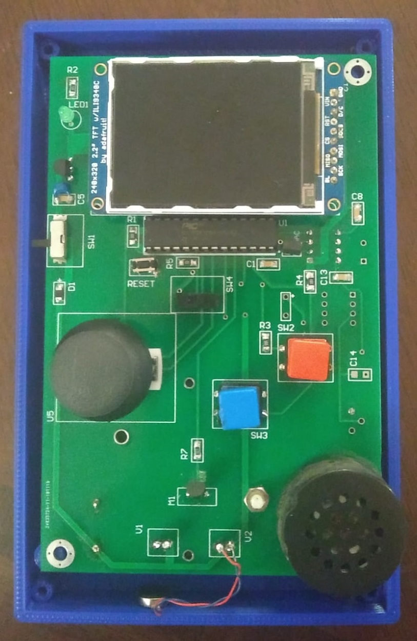
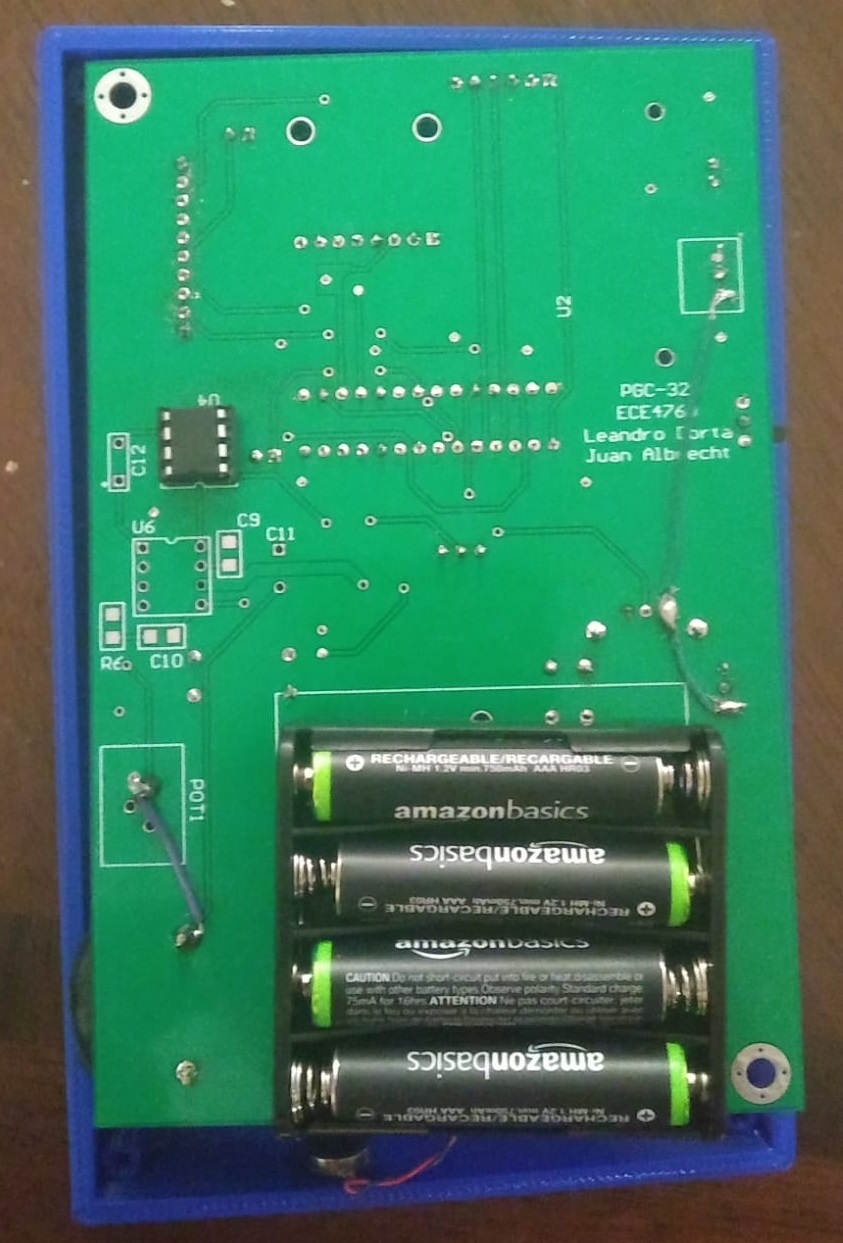
The printed circuit board also includes through hole components, specially the inclusion of multipler pin headers of different configuration for the programmer and the mounting of the TFT display and the MPU 6050 accelerometer for instance. Other through hole components are the push buttons, MCP1702 linear regulator (TO-92), 2N3904 NPN (TO-92), and a 3-pin pontentiometer. In the case of ICs (integrated circuits), our system includes the PIC32 microcontroller (28 pins), MPC4802 DAC (8 pins), and LM386 audio amplifier (8 pins); all these were used in DIP packages so the footprints are for the sockets. The use of DIP packages facilitates the replacement of broken ICs. An important observation of this design is the inclusion of the accelerometer underneath the TFT screen; this takes advantage of the height of the TFT display and saves space in the layout.
Components such as the joystick and the battery holder (4 AAA batteries) have specific footprints. Therefore, for the creation of these footprints the respective datasheets were taken as reference.
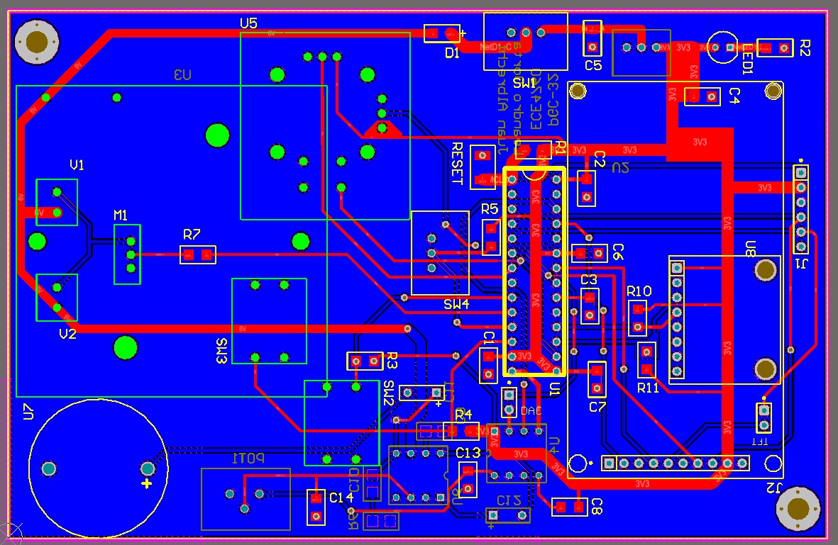
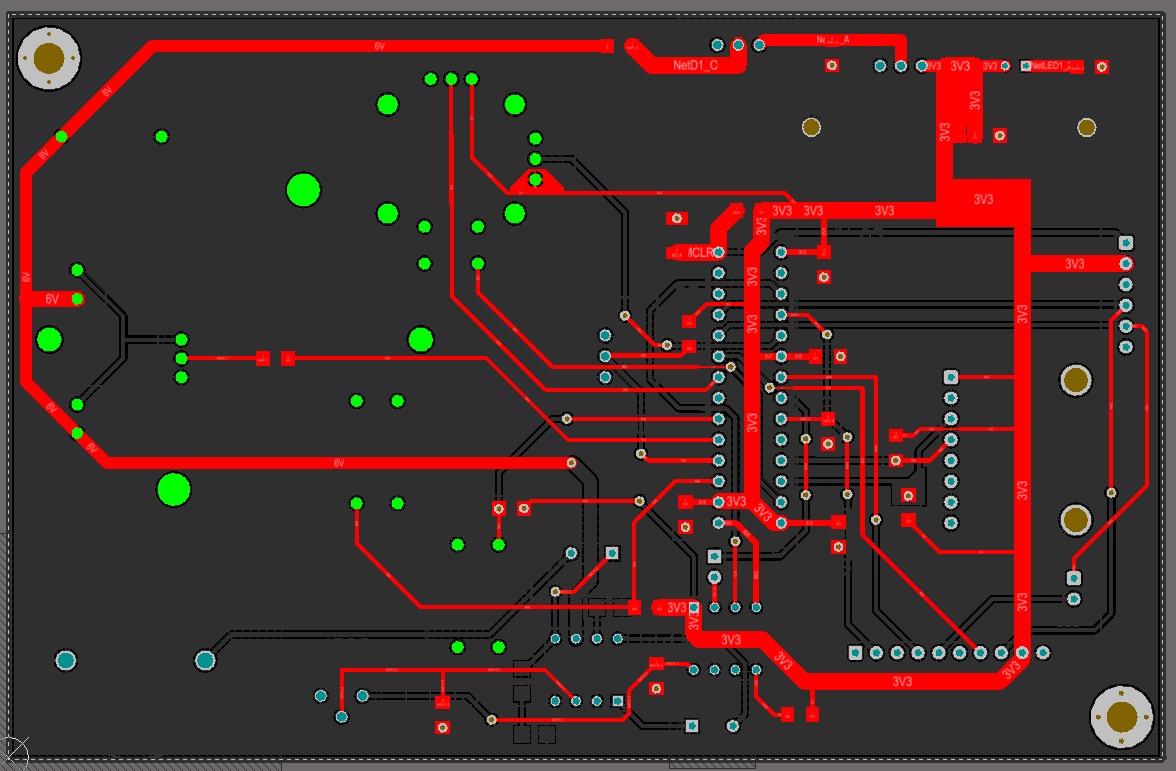
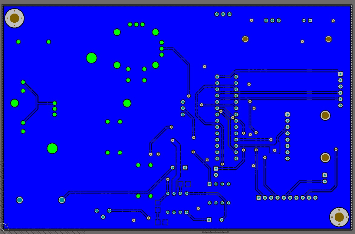
In the development of the printed circuit board, the bottom layer acts as ground plane. This is purposedly designed in this way because of all the advantages that using a ground plane offers: low-impedance ground connection, EMI shielding, acts as a heat sink, etc. It is also important to point out that for the placement of the components in the layout we took in consideration the separation of analog and digital systems to avoid corruption of analog readings by the noise produced by digital systems. In order to avoid cross-talking effects, an offset of at least 10 mils between traces. For the mounting of the printed circuit board on the bottom case, we placed two mounting holes of 150 mils of diameter placed diagonally at the top right and bottom left corners.
To conclude, the width of the traces ranges from 20 to 80 mils depending on the amount of current expected to pass through. Our system is rated to a maximum of 250 mA, which is established by the MCP1702 linear regulator
Top layer
Bottom layer
Gameplay
The idea behind the design of the game was based on the availability of features we had as part of our portable console. Since we incorporated a joystick that provides position values in the x axis and y axis, we thought about creating a controllable object that can move sideways (x axis) and also change velocity (y axis). Keep in mind that with the graphics of the TFT screen, it is very complex to have 3D graphics, therefore we limited the game to only two dimensions. After searching the web for some inspiration, we came across this clever game called Snakes vs Blocks and we wanted to try out something similar. We immediately discarded having the same format as this popular app game not only because of copywright issues, but also because it would be more difficult to account for dynamics of ball movement when drifting from side to side. Also, we could not think of any functionality for the pushbuttons or the y-axis of the joystick or accelerometer. Instead, we decided to draw a plane that could hold a certain amount of bullets and could shoot bricks in order to destroy them and keep traveling. Inside the game there are three types of features: bricks that destroy the plane (yellow), bricks that provide bullets for the plane (green), and circles (blue) that appear with less frequency which let the plane destroy all the obstacles in the screen in case of a difficult scenario. The following three features are shown below:
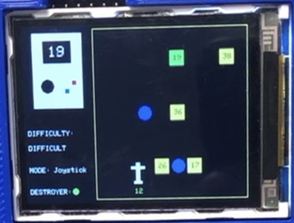
As it can also be seen in the picture above of the game's playing screen, the playground is squared to the right while the game status is shown to the left. This status window shows the time remaining for the current game inside a clean drawing of our very same PGC-32. Instead of keeping a score, the player wins if he/she is still alive when the time runs out. If a bricks hits the plane while there is still time left, then the player loses the game. Also in the same status window, the game shows if the player has the destroyer special power available by showing a green small circle; if it is unavailable, a red circle is shown instead. Finally, it can also be seen on the screen that it indicates the current level of difficulty running the game: easy, medium, and hard. In the software section of the report it is carefully explained how these three levels were implemented.
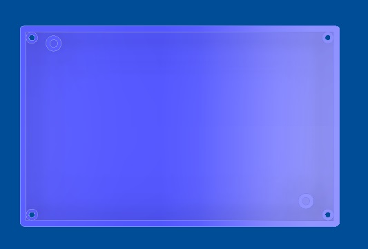
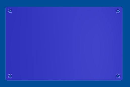
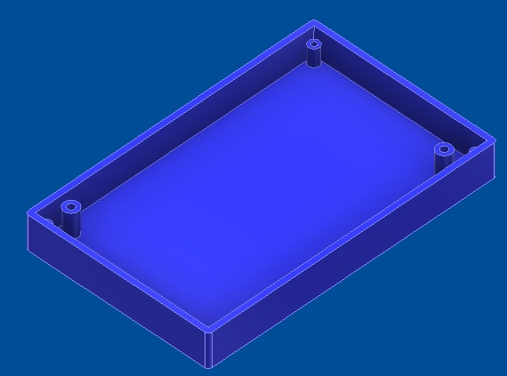
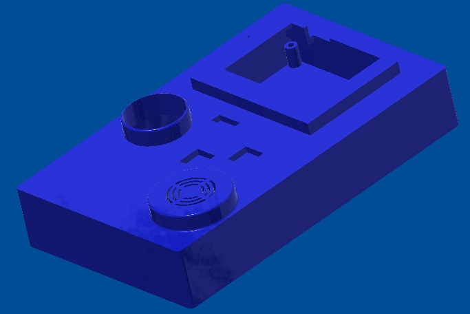
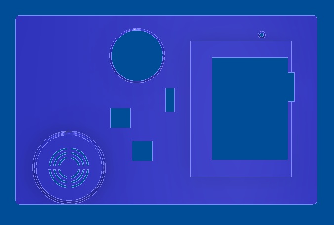
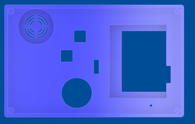
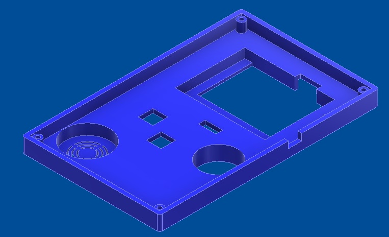
3-D Printed Case
The development of the case was based on the printed circuit board as reference. There are multiple components that interface with the top part of the case such as the joystick, push buttons, speaker, TFT display, pin header for programmer, and sliding switches. Among all these components, there are multiple different heights, which makes the design more difficult to develop; it also affects the manufacturing of it in the 3D printer, adding a great amount of supporting material. In the case of the bottom part of the case, it includes two extruded extenders for the mounting of the printed circuit board and other four extruded extenders for the assembly between the two parts of the case. There was an initial idea of including interfacing with the battery holder and the design of a piece to open and close this part of the case so the replacement of the batteries could be done with the printed circuit board enclosed in the case, but it was not possible for a matter of time. The mounting of the board on the bottom part can be done using 2 M3x2.5. Likewise, the assembly of the two case parts can be done by the use of four M3x2.5 wood screws of length approximated to 12 mm.
Top case
Bottom case