| # ( Hardware Design
)
|
| # Bipolar Stepper Motor
Control Circuit |
| A major hardware design task
in this project was to drive the bi-polar motors. These motors have no center
taps on their windings. Therefore, to reverse the direction of the magnetic
field produced by a coil, we need to reverse the current through the winding.
|
 |
| Fig
HW-1: Applied Motion Products, Inc. Scotts Valley 5017-935 bipolar
stepper motor |
| Each motor has four wires:
blue, red, white, and yellow. A test with a multimeter showed blue and red wires
both belong to a coil, while yellow and white are of another. After a survey of
stepper motor control materials, we decided to use the following circuit [1]: |
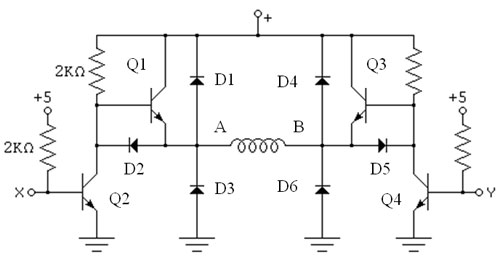 |
| Fig
HW-2: A Half H-Bridge Stepper Motor Control Circuit |
The circuit above is a half
H-bridge. It takes two of these circuits to control one motor. Point A and B are
connected to one coil of the motor, say blue and red wires. Point X and Y are
digital signals from the MCU, either at 5V or 0V. X xor Y is always 1, meaning
their logic values are complementary of one another at all times. Next we will
walk through two steps of the 4-step switching sequence to analyze the behavior
of the circuit:
- First X = 1: the base-emitter
junction of Q2 is forward-biased. Current flows from the collector to the
emitter via the base. - At the same time Y = 0: Q4 is off and current flowing
from +V through the resistor to the base of Q3 has nowhere to go. This current
therefore raises the voltage at the base of Q3, turning it on.
>> So for XY = 10, current flows from +V down Q3 to the coil from B to
A and to ground via Q2.
- Similarly, for XY = 01,
current flows from +V down Q1 to the coil from A to B and to ground via Q4.
The next two
steps operate on the other coil in a similar manner. Table HW-3 [3] below
summarizes the 4-step switching sequence for counterclockwise rotation: |
| Step |
Blue |
Red |
White |
Yellow |
| 1 |
0V |
5V |
5V |
0V |
| 2 |
5V |
0V |
5V |
0V |
| 3 |
5V |
0V |
0V |
5V |
| 4 |
0V |
5V |
0V |
5V | | |
| Fig
HW-3: Switching sequence for counterclockwise rotation |
Diodes D1, D3, D4, and D6
provide protection for the circuit against inductive kicks caused by abrupt
change in current when switching one step to another, given by the equation V =
-L(dI/dt). For an abrupt change in current (transistor switching), dI/dt is very
large, producing a large voltage across AB. When VA or VB
is larger than +V, current is shorted to the positive terminal via diodes D1 or
D4. When VA or VB is more negative than ground, current
is shorted to ground via diode D3 or D6.
For this circuit, we use 1N4001 for all the diodes and NPN TIP31 for
all the transistors.
|
| # Light Sensing Circuit |
| The next module is the light
sensing circuit. This circuit consists of two photocells mounted on either side
of the vehicle. The photocell produces a variable resistance based on light
intensity. We connect it in series with a fixed resistor between 5V and ground
to make a voltage divider circuit as follows: |
 |
| Fig
HW-4: Light sensing circuit for one sensor. r = 330 ohms. Photocell =
500 ohms (light) ~ 1500 ohms (dark). |
The photocell gives a low
resistance under a bright light and a high resistance in the dark.
Ain
= 5V(r/(R+r)) R is small (light), then Ain is large and vice versa.
Ain is connected to the MCU's A/D inputs to convert this voltage to a
number between 0 and 255. If this number is larger than some threshold value,
appropriate control signals are sent to the H-bridge circuits, actuating the
motors. |
| # Implementation of Circuits |
We implemented the circuits
for the following module as follows:
Mega32: We built a
prototype board for mobility. We learned to solder printed circuit boards for
the first time. We followed the guidelines given on [2]. We did not include
MAX233 and RS232 connector because no serial communication was needed. In
addition to the power connector, we also soldered a 9V clip so the board can be
powered by battery.
Stepper Motors: For the H-bridge circuit (Fig HW-2), we first wired it
up on white boards. We tested it and verified that it was functional. However
since the circuit had 19 I/O and power pins, we decided to transfer the circuit
to a large solder board to avoid wires coming loose when the car was moving or
being handled. Being new at soldering, we made a few mistakes of wires or pins
being not fully intact where they were supposed to make contact. We learned to
debug circuits this way. This H-bridge circuit also has two 9V clips attached in
parallel. So the motors can be powered by a 9V battery, or two of them for added
power.
Light Sensors: Two light sensing circuits (Fig HW-4) were wired up on a
white board. These circuits are simple and can be visually checked for loose
connections. Having them on a white board, the sensors can easily be moved
closer together or farther apart depending on the light source and the
environment.
|