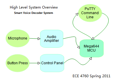
In our final project, we created a smart voice decoder system
that is capable of recognizing vowels in human speech. The audio
input is sampled through a microphone/amplifier circuit and
analyzed in real time using the Mega644 MCU. The user can record
and analyze his/her speech using both hardware buttons and custom
commands through PuTTY. In addition, the final product also
supports a simple voice password system where the user can set a
sequence of vowels as password to protect a message via PuTTY.
The message can be decoded by repeating the same sequence via the
microphone.
Some of the topics explored in this project are: Fast Walsh
Transform, sampling theorems and human speech analysis.
Here is a video summary of our project
High Level Design
Design Rationale
The idea of our project stemmed from seeing one of the previous
ECE 4760 final projects, Musical Water Fountain. In their project
, they used Fast Walsh Transform to analyze audio signal
generated by a MP3 player (shown in table below).
LED
0
1
2
3
4
5
6
7
Freq
0-170
170-310
310-420
420-560
560-680
680-820
820-930
930-10000
Then they would turn on the LED that corresponded to the most
energetic frequency division in the input frequency spectrum.
This made us wonder if identifying speech is possibly by a method
similar to this.
In fact, with today's technology, speech recognition is fully
realizable and can even be fully synthesized. However, most of the
software that deals with speech recognition require extensive
computation and are very expensive. With the limited computation
power of mega644 and a $75 project budget, we wanted to make a
simple, smart voice recognition system that is capable of
recognizing simple vowels.
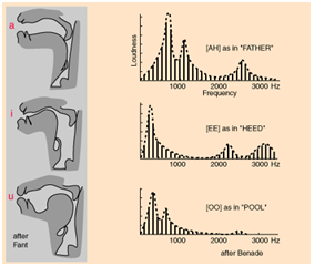
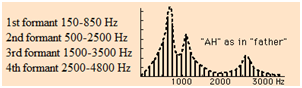
After careful research and several discussions with Bruce, we
found that vowels can be characterized by 3 distinct peaks in
their frequency spectrum. This means if we perform a transform
to input speech signal, the frequency spectrum profile will
contain characteristic peaks that correspond to the most
energetic frequency component. Then if we check to see if the 3
peaks in the input fall in the ranges we defined for a specific
vowel, we will be able to deduce is that vowel component was
present or not in the user's speech.
Logical Structure
The main structure of our decoder system centers on the mega644
MCU. Our program allows the MCU to coordinate commands being
placed by the user via PuTTY and the button panel while analyzing
the user's audio input in real time. On the lowest design level
(hardware), we have microphone and a button panel to convert
physical inputs by the user into analog and digital signals the
MCU can react to. On the highest level, PuTTY displays the
operation status of the MCU and informs the MCU of user commands
being placed at the command line. PuTTY also offers user the
freedom to test the accuracy of our recognition and simulates a
security system where the user must say a specific sequence of
vowels to see a secret message.
Mathematical Theory
Vocal Formats
Basically, the first three formant frequencies (refer to
peaks in harmonic spectrum of a complex sound) can attribute to
the different appeal of vowel sounds.
Therefore, if we can pick out formant by intensities in
different frequency ranges, we can identify a vowel sound and
use sequence of vowel to generate an audio pass code specific
to that vowel.
Frequency Transform Algorithms
The biggest difference between our analysis
and musical intensity is that we need to adjust the frequency
range stated above to better tell apart the difference between
several peaks and combine all other information including
amplitude. We need to decide which frequency transform
algorithm is better to be used for a real-time audio
addressing in both accuracy and computation speed. In fixed
point DSP function in GCC, DCT, FFT & FWT are several common
used algorithms. In our case, we chose Fast Walsh Transform
over the rest simply because of its speed and its linear
proportionality to Fast Fourier Transform.
The Fast Walsh Transform converts the input waveform into
orthogonal square waves of different frequencies. Since we
are only working with voice ranges here, we set the sample
frequency to 7.8K which allows us to detect (ideally) up to
3.8kHz. We also knew that the lowest fundamental frequency
of human voice is about 80-125Hz. Thus, we chose a sample
size of 64 bit. This generates 32 frequency elements equally
spaced from 0Hz to 3.8kHz (not including the DC component).
The individual frequency division width is 3.8k/32=118.75Hz
which gives maximizes our frequency division usage (since we
could have useful information in every division instead of
say a division width of 50Hz, where the first division does
not provide useful information). Furthermore, this choice also
minimizes our computation time since the more samples we
have to compute, the more time it will take for the MCU to
process input audio data.
MATLAB Simulation Results
In this part, most research we did were based on common
vowel characters like 'A','E','I','O','U', which demonstrated
that the method we attempt to develop could achieve. Yet in
the real case, we found that the difference of these five
characters is not as obvious as simply comparison between
frequency sequency could distinguish.
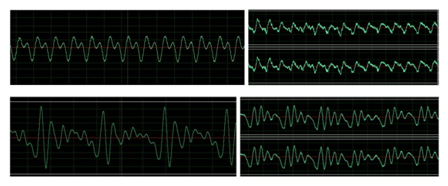
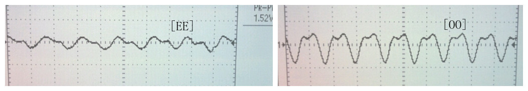
We first use Adobe Audition to observe initial input
waveform taken directly from Microphone and AT&T text2speech
as shown in the picture. Although the waveform corresponding
to the same vowel would result in a similar shape, there still
exists difference which we may find more straightforward in
frequency domain.
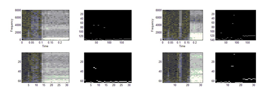
The first program in MATLAB is based on Prof. Land's code
that compares the FFT and FWT outputs as spectrograms, then
takes the maximum of each time sliced transform and compares
these spectrograms. Top row is FFT power spectrum, FWT sequency
spectrum is in the bottom. The maximum intensity coefficient
of each spectrogram time slice in FFT and FWT are almost in
the same shape. We'll take one spectrum as an example.
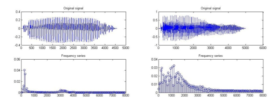
Another program directly implements FFT and show a frequency
series. In this figure we can clearly see the resonance peaks of
a vowel. This transform is 256 points. Also, notice that because
of noise interference, it would be hard to tell apart the second
peak for [EE] and this is not the only case.
Hardware/Software Tradeoffs
Due to the limited precision of our Fast Fourier Transform,
frequencies that differ by a value that is less than the width
of our frequency division are often not distinguished. When
dealing with boundary frequencies, this was a problem for us
since the peak frequency did not always reside in the same
frequency division. To improve upon this, we used multiple
divisions but we still had errors since we cannot consider
every possible boundary case. We improved upon this further
by boosting the gain of our op amp from x10 to x100. This
boast gave us a much better summary result and reduced our
error. However occasionally, we still have errors that stem
from the precision of our analysis tool.
Relations to IEEE Standards
The only standard applicable to our design is the RS232
serial communication protocol. We used a MAX233 level shifter
and a custom RS232 PCB designed by Bruce Land.
Relevant Copyrights Trademarks and Patents
The mathematical theories for frequency analysis of audio
signals were obtained from both discussions with Bruce Land
as well as R. Nave's
webpage from Georgia State University.
Hardware Design
Overview
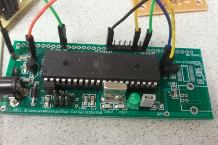
Our hardware setup consists of a prototype board that hosts
the MCU and three other individual function panels. Audio
input is processed through the amplifier panel and sampled by
the MCU. The RS232 board allows the state of the MCU and user
input to be sent to the PuTTY. The last function panel allows
user to change the current operating mode of the MCU and
enables the audio input to be sampled or discarded in the
main program.
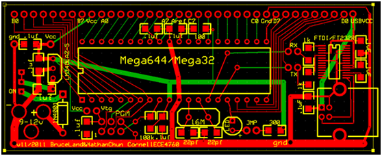
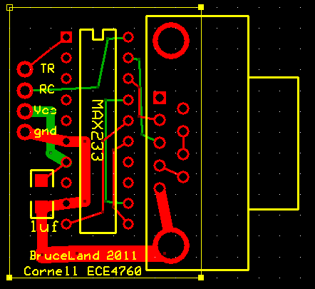
ECE 4760 Custom PCB
The prototype board we used is the mega644 prototype board
design by Bruce Land. The printed PCB layout is shown below.
The only port pins used (soldered) are C0,C1,C7 and A0. We also
had to solder RX and TX pins to enable RS232 serial communication.
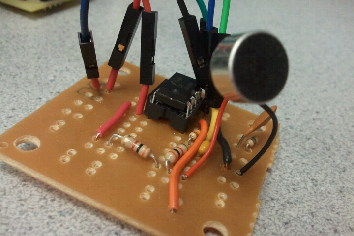
Audio Amplifier Circuit Panel
The amplifier circuit used is shown below. The microphone used
in this project uses a charged capacitor to detect vibrations in
air. As a result, R2 provides the DC bias necessary to maintain
the charge across the internal capacitor of the microphone to
allow sounds to be converted to electrical energy. R1 provides
the DC bias that the microphone needs to remain functional. The
LM358 op amp operates as a 2 stage signal filter. The negative
voltage input of the op amp is first passed through a low pass
filter with a time constant of approximately 42microSec. This is the
upper bound of our audio signal filter since normal human speech
lies between 85Hz to 3kHz. The value of the parallel
resistor/capacitor feedback circuit is determined by the gain
we wanted to achieve. In our case, we chose the amplifier gain
to be 100, thus the value of R4 we chose is 1M Ohms (100 times
R3) and C2 is chosen to compliment the operating frequency of
less than 3kHz. The output of the op amp is fed to the analog
compare input of the MCU (PINA.0) and analyzed at a rate of
7.8kHz.
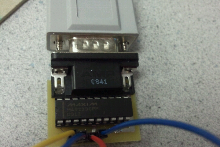
RS232 Serial Communciation Panel
To better user experience with our design, we decided to use
serial communication via PuTTY to inform the user of the current
operating state of the program. We also felt that it would be a
lot more convenient if the user could control the program via
both hardware as well as software. To enable serial communication
between the MCU and a PC, we used the Max233CPP level shifter
chip and the RS232 connector PCB Bruce had designed. The transmit
and receive pins on the MCU prototype board are connected to the
TR and RC pins on the RS232 board to enable communication.
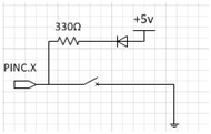
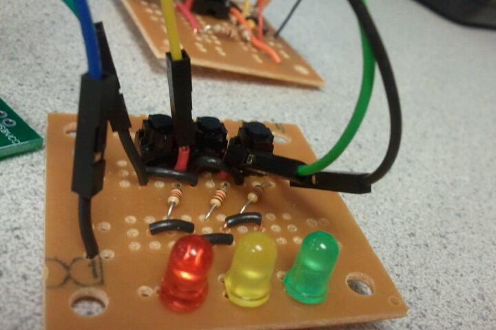
Hardware User Interface (Control Buttons)
Our hardware user interface consists of 3 buttons and 3
indication lights. When a button is held down, the corresponding
LED will turn on. In our setup, pressing the green LED/button
combination displays the results summary on the PuTTY screen.
Pressing the yellow LED/button combination begins the sampling
the MCU. Analysis on the input data is performed when this button
is released (see code below for details). Each button is signaled
by a pin in PORTC. The red LED/button combination allows the
user to change the operating mode of the program between testing
mode and decoding mode. The switch/LED circuitry for 1 button is
shown to the right. When the button is pulled low (i.e. pressed)
the LED is connected to ground via a 1k resistor and lights up.
Software Design
Overview
Overall, the program is broken down as follows:
Serial communication-take user input & display result
Button state machine-for test/demo mode user interface
FWT transform analysis-provide frequency ranges of input waveform
Vowel recognition-analyze vowel spectra and identify
Decode-check whether input vowel sequence is what we expected
Initialize
There are 7 header files and 1 source file included. "uart.h"
& "uart.c" are used for UART driver. specify basic function for GCC compiler.
provides context for handling interrupts.
provides interfaces for a program to access data
stored in program space of the device.
Variables initialized can be divided into four modules. One for
FWT algorithm contains fixed number, size of FWT, frequency range
specification. One for button state machine defines timer and
button state. The third and fourth modules consist of
characteristic specification, vowel counters, passcode setting,
and passcode comparison. Besides, in the void initialize()
function, UART is initialized and timer0 is set up to sample A/D.
We also need to enable ADC, set pre-scalar, clear interrupt
enable and prepare to start a conversion.
The sampling frequency we chose at the analog input is 7.8kHz.
Since the highest voice fre quency is about 3.5kHz, 7.8kHz
sampling rate gives us a reasonable upper bound.
Interrup Service Routines (ISR)
ISR(TIMER0_OVF_vect)
There is only 1 interrupt service routine used in this project:
timer0 overflow ISR. Timer0 is used to read A/D converter and
update appropriate buffer. We also use timer0 to maintain 1ms
tick for all other timing in this program, including two button
state machine and a monitor. Each button monitor program gets
executed every 30 machine cycle, this was purposely chosen to
make user interactions run noticeably smooth.
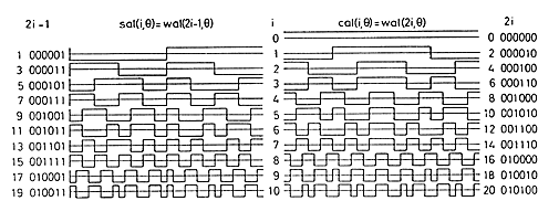
Task Breakdown
FWT transform to sequency order
This part is based on Prof. Land's code, which attempts to
light up LEDs corresponding to which sequency bands have the most
energy. The program takes a 64 points FWT as a sample rate of 7.8
kHz, throws the DC component, adds the absolute value of the sal
and cal components. This gives us 33 frequency divisions equally
spaced from 0Hz to 3.8kHz. The value stored in each frequency
division is proportional to its energy level in the sampled data.
This is used later to identify the characteristic peaks
(most energetic frequency component) of vowels.
voidFWTfix(int x[])
This function does forward transform only, and useFWTreorder()
to put the transform in sequency order.
voidFWTreorder(int x[], const prog_unit8_t r[])
This function converts from dyadic order to sequency order.
void transform(void)
This function can be divided into two parts. The first part
computes FWT transform, updates the FWT, generates a sequency
order, combines sal&cal, an omits DC in ain[0]. We will talk
about the second part later.
Serial Communciation
voidserialComm(void)
This part takes user input and defines all the system
behaviors in user interface including: s=set passcode; r=reset
current entry; p=print passcode stored; t=enter testing mode. As
the whole system has two modes (test/demo), and three processes
(passcode setting->vowel recognition->decoding). It first checks
if system is current in the state of waiting for entry. Then for
"s" command, it calls intstringtoint(char)to store corresponding
number into an array passcode[ ], in which ah: 1; oo: 2; oh: 3;
ae: 4; ee:5. When "r" is entered as command, system cleared
current entry (result[]) and let the user decode again. Command
"p" would print out current passcode for testing. We also add a
testing mode for verifying the vowel recognition preciseness.
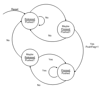
Button State Machine
This part is responsible for describing all the states selected
button may go through involving MaybePush, NoPush, Pushedand
executes 30 machine cycles. Every time when called by main, it
resets task timer, detect push state and change push flag.
Notice that we had set three buttons marked by green, yellow,
& red LEDs, and for each of them, we have a button state machine.
voidbuttonMon(void)
This state machine corresponds to PINC=0xfe and time1. When
yellow button is pushed, the system is informed that a new audio
extraction process is started. The function clears all previous
entries and set PushFlag to 1.
voidplayBackMon(void)
This state machine corresponds to PINC=0x7f and time2. When
green button is pushed, the system is informed that all the audio
extraction process is completed. The function analyzes all
previous entries and set playBackFlag to 1.
voidstateMon(void)
This state machine monitors current device operation state.
When red button is pushed, the system is informed that user needs
to switch to a demo mode and begin a passcode debugging.
Vowel Recognition
void transform(void)
This second part of this function uses 3 predefined
characteristic vowel peaks ranges for each vowel and calculates
three characteristics of input waveform. The following algorithm
is based on experimental research. We first choose "ah", "oo",
"oh", "ae", "ee" as passcode elements. This method is similar to
but not the same as purely identifying vowels based on its ideal
frequency peaks. This is because some of the vowels such as "ee"
and "oh" have very similar transform results. If only the ideal
frequency peaks are compared and analyzed, we cannot effectively
identify what the user has said. Instead, we experimentally
determined the frequency divisions that occur most uniquely to
the particular vowel (shows up many times in the transformed
signal but is rarely present in other vowel signals).Then for
each element, we compare the analyzed FWT results with the peak
ranges we have defined and we increment a corresponding vowel
counter when that particular vowel has been detected. For example
, the characteristic peaks we chose for "ae" locates in the 3rd,
5-12th,12-28th range of the sequence order, while for "oh", the
range is changed to 4-7th, 8-11th, 21-31st.
In addition to determining the frequency ranges to use
experimentally, we also had a threshold value that is used to
compare with the amplitude of the first peak in FWT analysis.
For any transform performed with maximum peak amplitude below
this threshold, we discard the transformed result. This is
because if the amplitude of the first peak is not high enough,
we will not be able to detect the second or third peak since
amplitude of first peak > amplitude of second peak>amplitude of
third peak.
This function also lights up a LED as transforming signal.
intfindMax(int x[],int i)
This routine returns a maximum value in a following sequence.
intfindMin(int x[],int i)
This routine returns a minimum value in a following sequence.
int recognize(void)
We initialized 5 counters for vowels and calculate the
possibility of each in recognition. The one with the maximum
counter number is considered as the correct answer and returned
by this function.
Decoding
A comparison between passcode[] & result[] is implemented to
proceed decoding.
void display(int t)
This is an additional function called by Main in test mode,
when vowel recognition is completed and we need a result display
on screen.
Delegating Task Using Main Function
First, initialize() is called to establish register, port
configurations on the MCU as well as to start timers and ISRs.
Immediately after, it calls serial communication to begin our
first command. Then we enter an endless loop which controlled the
tasks to be executed based on the timer values and are responsible
for resetting the timer values before each of the tasks are
called. Note that for each loop, we have to detect whether a
button is pushed and which mode the system is working under.
In demo mode, a message is displayed on screen indicating that
audio input can be started. Each time an audio is extracted, the
system returns the recognition result of the vowel. After 5 times
of extraction which is exactly the length of a passcode, the
system checks whether the sequence is correct, displays the
result and prints out "Congratulations" or "Decoding failed".
While in test mode, the system just proceed with a simple
extraction and recognition process.
Things we tried but did not work :(
Narrow the Search for Peaks Using MATLAB
We tried using MATLAB's fft function to identify the first 3
characteristic peaks of the vowels. We were hoping that by
simulating the same voice waveform in MATLAB, we can be sure of
the peaks we are looking for in our MCU program. However, the
results were not satisfactory and the peaks produced cannot be
easily distinguished. Furthermore, depending on the person
speaking, the analysis results that came from MATLAB differed
greatly. We later switched our algorithm by finding the most
frequent element in the vowel's FWT output. Even though these 2
methods are very similar, in the case of boundary frequencies,
the second method produced a much more reliable result.
Results
Execution
Despite the fact that we are processing and analyzing data in
real time, the FWT analysis and summary were produced
instantaneously after the release of the yellow button. There are
no known errors associated with controlling the MCU operation via
both PuTTY and the physical button panel. Even when 2 buttons are
pressed at the same time, the system will sequentially execute
the valid commands.
Here are some screen shots of our system during operation:
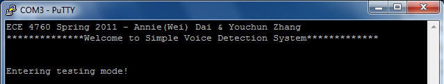
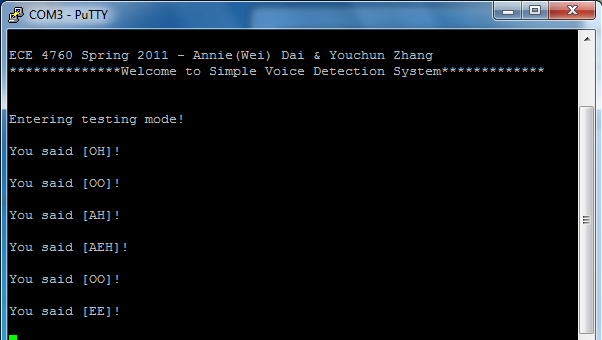
When the system is turned on, our MCU automatically enters the
default testing mode. At the same time, PuTTY will display a
welcome screen informing the user that the system is ready to
take inputs.
In the testing mode, the user is able to see the summary
results of only saying 1 vowel. Audio input is processed when
the user holds down the yellow button while speaking into the
microphone. When the yellow button is released, the program will
automatically compute the FWT and display the prediction in PuTTY.
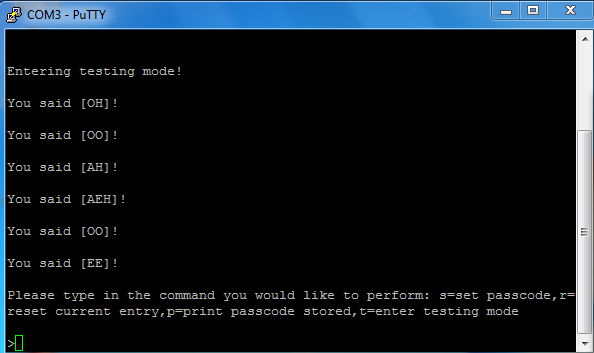
To leave testing mode, the user can just press and release the
red button once. As shown below, PuTTY shows that the program has
exited testing mode and entered the decoding mode.
In the decoding mode, the user can set a sequence of 5 vowels
as the system password and repeat the same sequence via the
microphone while holding down the yellow record button.
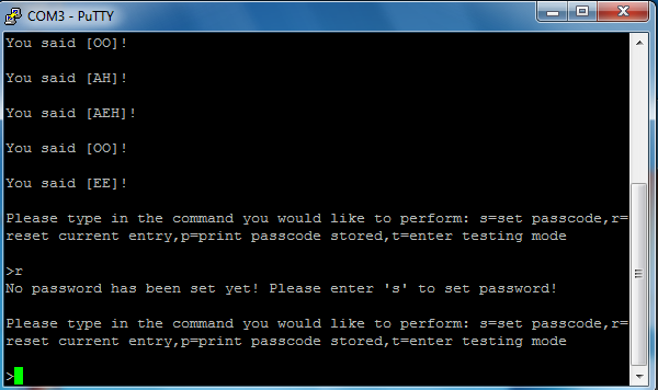
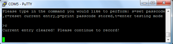
If the user accidently entered the reset command before setting
a password, the system will inform the user that there is no
valid password being stored at the time. The user should set
the password first by entering 's' to the command line.
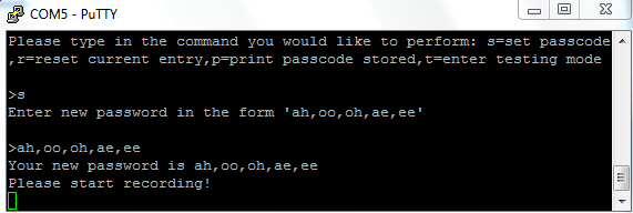
New password is entered by inputting the vowel sequence with
commas separating each vowel input. Once entered, the system will
display the entered result and automatically enter recording mode
where the MCU simply waits for user's audio input.
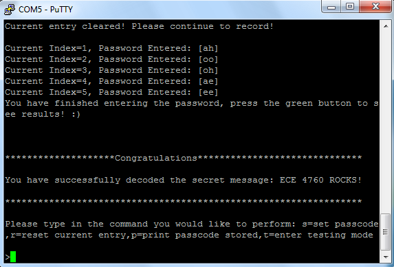
If the input audio sequence agrees with the stored password,
then the congratulations screen will appear along with the secret
message.
Anytime there is a command prompt at PuTTY, the user can choose
to reset his/her current audio input by entering 'r'. This erases
all of the audio inputs stored so far in the system and allows
the user to re-record the password again.
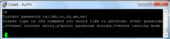
Anytime there is a command prompt at PuTTY, the user can see
the stored system password by entering 'p' for print. The system
will display the entered vowel sequence.
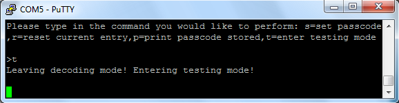
The user can reenter testing mode from decoding mode by
entering 't' at the PuTTY command line.
Here are 2 videos demonstrating our system at work
Performance
We originally designed our program to decode female voices.
However, when we tested our system, we discovered that it decodes
male voices (of much lower fundamental frequency) just as
accurate as it decodes female voices. However, due to the limited
precision of the FWT we implemented, in cases where the frequency
peaks are near our predefined characteristic peak value for a
vowel, errors occasionally occur.
We tested our program with a
couple of our friends and for a male voice, the program is able
to accurately predict the vowel said 49/50 times and for female
voices, the program is able to accurately predict 45/50 times.
Furthermore, the program only accurately recognizes vowel is the
user is consistent in speaking (no accents or instability during
recording).
We also found that the MCU tend to confuse between "OO" and
"EE" or "OH" and "AE". In the case of "OO" and "EE", the
waveforms are very similar. In the FWT output, both vowels have
peaks that often overlap. In our program, "OO" and "EE" are
determined by the maximum amplitude obtained in the transform.
In normal speech, "OO" is louder and "EE" (see below for
waveform comparison). This explains why MCU mistakes one for
the other.
In the case of "OH" and "AE", FWT of the input waveforms
produce almost the same first and second peaks. The two vowels
are distinguished mainly based on the location of the third peak.
However, the amplitude of the third peak is relatively low and
can be easily mixed up with noise. Thus, predictions made about
"AE" and "OH" and differ greatly depending how the speech was
formulated.
Here are some test results we got using our system:
MCU Confusion for\Expectation
ah
oh
oo
ae
ee
Female
--
--
--
oh
oo
Male
oh
ae
--
--
--
MCU's Prediction Accuracy
95%
90%
95%
94%
90%
Safety and Usability
The system that we have designed can be used as a basis for
implementing speech recognition since speech consists of vowels
and consonants that can be identified using frequency analysis.
An example of possible implementation in the real world would be
using speech recognition in security systems, something that
could be more convenient than entering passwords on a keypad to
people with less proficient vision.
Furthermore, our system is simple and easily to handle. The
only precaution in using our prototype system is the user must be
careful in touching the PCB and port pins to minimize ESD hits.
Conclusion
Expectation
Overall, our final project result achieved all of the goals
we defined in our project proposal. Our speech recognition system
is able to accurately identify the vowel user has said. We
extended this implementation and simulated a security system
where the user must say the vowels in a particular sequence to
be able to decode a secret message.
Future Improvements
There are two improvements that can be made in the future.
The first one is based on current preciseness. Although our
system in recognizing five vowels is clear and fits most users,
we still need more experimental simulation to help identify
characteristics and narrow the search for peaks in vowels.
Furthermore, we may develop more characteristics for other vowels
and even those not-vowel sounds. This also requires more research
on vowel classification.
Another progress would be more complicated word recognition if
we've done all the vowel identification. Since we are already
able to tell apart five basic vowels, and for most words, an
interesting thing is that you can pronounce and classify them
with a sequence of basic vowels. For instance, the waveform of
"yes" is similar to [ae] and [ee], while when one pronounce "no"
, you can simply tell it apart by [oh]. Besides, for a word like
"starbucks", the [ah] sound is obvious inside. Yet the difficulty
for a word recognition even just based on sequence of vowels is
that our current method is based on a cumulatingpossibility which
is not strictly corresponding to time. In this way, the
algorithm we implement in decoding is no longer useful. We may
need to consider another cumulating possibility for all the
words that may sound alike and mark the most possible one as
result. This may lead to big challenge in accuracy.
Ethical Considerations
We have done our best effort to conform to the IEEE code of
Ethics in the design and execution of our project. The FWT
algorithm we used in our design was written by Bruce Land. The
button state machines we used were modified code from previous
lab exercises. There are no known systems using a similar MCU
in implementing vowel recognition system. In fact, much of the
speech recognition systems available in the world today require
a lot more computation power than the mega644 and is able to
analyze much more complex voice inputs.
We are honest in reporting the result of our system and our
summary results are as accurate as the precision and real time
computation capability the MCU can allow.
This system can be used to implement a security system with
speech recognition. This can be potentially more convenient for
people with less proficient vision than a keypad security system.
Furthermore, with more computation power, our system can
recognize individual voices and much more complex voice inputs.
Legal Considerations
Our project is a simple audio input and addressing device. It
would not cause any interference with other devices and won't
result in any violation of regulation.