Overall, the program is broken down as follows:
A Smart Voice Decoder System for Vowels
By: Annie (Wei) Dai (wd65@cornell.edu) and Youchun Zhang (yz526@cornell.edu)

Software Design
Overview
Initialize
There are 7 header files and 1 source file included. "uart.h"
& "uart.c" are used for UART driver. Variables initialized can be divided into four modules. One for
FWT algorithm contains fixed number, size of FWT, frequency range
specification. One for button state machine defines timer and
button state. The third and fourth modules consist of
characteristic specification, vowel counters, passcode setting,
and passcode comparison. Besides, in the void initialize()
function, UART is initialized and timer0 is set up to sample A/D.
We also need to enable ADC, set pre-scalar, clear interrupt
enable and prepare to start a conversion.
The sampling frequency we chose at the analog input is 7.8kHz.
Since the highest voice fre quency is about 3.5kHz, 7.8kHz
sampling rate gives us a reasonable upper bound.
Interrup Service Routines (ISR)
ISR(TIMER0_OVF_vect)
There is only 1 interrupt service routine used in this project: timer0 overflow ISR. Timer0 is used to read A/D converter and update appropriate buffer. We also use timer0 to maintain 1ms tick for all other timing in this program, including two button state machine and a monitor. Each button monitor program gets executed every 30 machine cycle, this was purposely chosen to make user interactions run noticeably smooth.
Task Breakdown
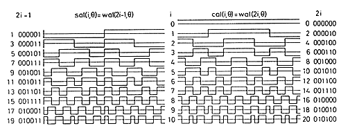
FWT transform to sequency order
This part is based on Prof. Land's code, which attempts to light up LEDs corresponding to which sequency bands have the most energy. The program takes a 64 points FWT as a sample rate of 7.8 kHz, throws the DC component, adds the absolute value of the sal and cal components. This gives us 33 frequency divisions equally spaced from 0Hz to 3.8kHz. The value stored in each frequency division is proportional to its energy level in the sampled data. This is used later to identify the characteristic peaks (most energetic frequency component) of vowels.
voidFWTfix(int x[])
This function does forward transform only, and useFWTreorder() to put the transform in sequency order.
voidFWTreorder(int x[], const prog_unit8_t r[])
This function converts from dyadic order to sequency order.
void transform(void)
This function can be divided into two parts. The first part computes FWT transform, updates the FWT, generates a sequency order, combines sal&cal, an omits DC in ain[0]. We will talk about the second part later.
Serial Communciation
voidserialComm(void)
This part takes user input and defines all the system behaviors in user interface including: s=set passcode; r=reset current entry; p=print passcode stored; t=enter testing mode. As the whole system has two modes (test/demo), and three processes (passcode setting->vowel recognition->decoding). It first checks if system is current in the state of waiting for entry. Then for "s" command, it calls intstringtoint(char)to store corresponding number into an array passcode[ ], in which ah: 1; oo: 2; oh: 3; ae: 4; ee:5. When "r" is entered as command, system cleared current entry (result[]) and let the user decode again. Command "p" would print out current passcode for testing. We also add a testing mode for verifying the vowel recognition preciseness.
Button State Machine
This part is responsible for describing all the states selected button may go through involving MaybePush, NoPush, Pushedand executes 30 machine cycles. Every time when called by main, it resets task timer, detect push state and change push flag.
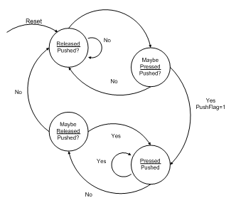
Notice that we had set three buttons marked by green, yellow, & red LEDs, and for each of them, we have a button state machine.
voidbuttonMon(void)
This state machine corresponds to PINC=0xfe and time1. When yellow button is pushed, the system is informed that a new audio extraction process is started. The function clears all previous entries and set PushFlag to 1.
voidplayBackMon(void)
This state machine corresponds to PINC=0x7f and time2. When green button is pushed, the system is informed that all the audio extraction process is completed. The function analyzes all previous entries and set playBackFlag to 1.
voidstateMon(void)
This state machine monitors current device operation state. When red button is pushed, the system is informed that user needs to switch to a demo mode and begin a passcode debugging.
Vowel Recognition
void transform(void)
This second part of this function uses 3 predefined characteristic vowel peaks ranges for each vowel and calculates three characteristics of input waveform. The following algorithm is based on experimental research. We first choose "ah", "oo", "oh", "ae", "ee" as passcode elements. This method is similar to but not the same as purely identifying vowels based on its ideal frequency peaks. This is because some of the vowels such as "ee" and "oh" have very similar transform results. If only the ideal frequency peaks are compared and analyzed, we cannot effectively identify what the user has said. Instead, we experimentally determined the frequency divisions that occur most uniquely to the particular vowel (shows up many times in the transformed signal but is rarely present in other vowel signals).Then for each element, we compare the analyzed FWT results with the peak ranges we have defined and we increment a corresponding vowel counter when that particular vowel has been detected. For example , the characteristic peaks we chose for "ae" locates in the 3rd, 5-12th,12-28th range of the sequence order, while for "oh", the range is changed to 4-7th, 8-11th, 21-31st.
In addition to determining the frequency ranges to use experimentally, we also had a threshold value that is used to compare with the amplitude of the first peak in FWT analysis. For any transform performed with maximum peak amplitude below this threshold, we discard the transformed result. This is because if the amplitude of the first peak is not high enough, we will not be able to detect the second or third peak since
amplitude of first peak > amplitude of second peak>amplitude of third peak.
if(max==3 && second>5 && second<12 && third<28 && third>12) aehCounter++;
if(max>4 && max<7 && second>8 && second<11 && third>21 && third<31) ohCounter++;
if((max==1) && second==5 && third>10 && third<14){
if(compare[max]>30) ooCounter++;
elseeeCounter++;
}
if((max==1 && (second>6 && second <10) && (third>=11 || third<=14))||(max==8 && second==24 && third>27 && third<31)) ahCounter++;
}
This function also lights up a LED as transforming signal.
intfindMax(int x[],int i)
This routine returns a maximum value in a following sequence.
intfindMin(int x[],int i)
This routine returns a minimum value in a following sequence.
int recognize(void)
We initialized 5 counters for vowels and calculate the possibility of each in recognition. The one with the maximum counter number is considered as the correct answer and returned by this function.
Decoding
A comparison between passcode[] & result[] is implemented to proceed decoding.
void display(int t)
This is an additional function called by Main in test mode, when vowel recognition is completed and we need a result display on screen.
Delegating Task Using Main Function
First, initialize() is called to establish register, port configurations on the MCU as well as to start timers and ISRs. Immediately after, it calls serial communication to begin our first command. Then we enter an endless loop which controlled the tasks to be executed based on the timer values and are responsible for resetting the timer values before each of the tasks are called. Note that for each loop, we have to detect whether a button is pushed and which mode the system is working under. In demo mode, a message is displayed on screen indicating that audio input can be started. Each time an audio is extracted, the system returns the recognition result of the vowel. After 5 times of extraction which is exactly the length of a passcode, the system checks whether the sequence is correct, displays the result and prints out "Congratulations" or "Decoding failed". While in test mode, the system just proceed with a simple extraction and recognition process.
Things we tried but did not work :(
Narrow the Search for Peaks Using MATLAB
We tried using MATLAB's fft function to identify the first 3 characteristic peaks of the vowels. We were hoping that by simulating the same voice waveform in MATLAB, we can be sure of the peaks we are looking for in our MCU program. However, the results were not satisfactory and the peaks produced cannot be easily distinguished. Furthermore, depending on the person speaking, the analysis results that came from MATLAB differed greatly. We later switched our algorithm by finding the most frequent element in the vowel's FWT output. Even though these 2 methods are very similar, in the case of boundary frequencies, the second method produced a much more reliable result.
Copyright ECE 4760 Spring 2011 Annie (Wei) Dai and Youchun Zhang
