|
Paint Brush Application
|
|
| Introduction
| High Level Design
| Hardware
| Software
| Interface
| Results
| Conclusion
| Appendix
| Downloads
|
|
|
|
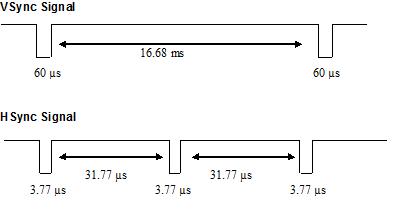
VGA A VGA controller to handle a VGA with the resolution of 640x480 with a color depth of 8 bits/pixel has been implemented. 3 bits each for the Red and the Blue components and 2 bits for the Green component. The VGA controller uses the SRAM as memory. The 512K bytes of SRAM can be used to store the pixel value of the 640 X 480 pixels. The SRAM is addressed by an 18 Bit address bus to access these values. Each location in the SRAM stores a 16 bit value that corresponds to two adjacent pixel values. 8 bits each pixel. The address bus is assigned value such that the most significant 9 bits are used for x-coordinate of the VGA and the lower 9 bits are used for the y-coordinate of the VGA. These values are got from the NIOS II Soft processor. The pixels on the VGA are illuminated by the vertical and horizontal sweeps made by the synchronization signals. The VSync and HSync synchronization signals are used for this purpose. The VGA Controller generates these synchronization signals based on the clock signal frequency. We have used a clock frequency of 27 MHz for the VGA adapter. The VSync is low for 60 microseconds every 16.68 milliseconds. The HSync is low for 3.77 microseconds every 21.77 microseconds. A new frame will be scanned into the VGA based on the VSync and HSync pulses of the VGA. The VGA needs full control of the SRAM when it sweeps through the frames. Hence a value is written to the SRAM only when either the VSync or the HSync are low. A lock bit is used to maintain this synchronization. The top level modules send in the appropriate RGB values to the VGA controller from the SRAM. The VGA controller then writes these data to the RGB channels of the VGA monitor. The VGA controller also handles the cursor movement. The position of the cursor is sent from the software. The NIOS PIOs x_cursor and y_cursor are used for this. The cursor type defined enables use of different cursor formats. Different cursor types can be used based on the input given to the cursor_typ, a NIOS PIO that interfaces to the software.
Figure 1: V Sync and H Sync signals The coordinates values x_ptr and y_ptr are sent from the NIOS II software module and are stored in the SRAM. These are used to address the memory at the word level. The higher 9 bits of the address bus are used for the X coordinates and the lower 9 bits are used for the Y coordinates. The x_ptr and y_ptr are 10 bits each. The upper 9 bits of x_ptr is used in the address bus for the x-coordinate. The last bit of the X coordinate is used to differentiate between a pair of adjacent even and odd pixel locations on the screen. An active low signal we Write Enable signal is used to decide if data can be written into the SRAM or read from the SRAM. If we signal is low then data can be written into the SRAM while if we signal is high then data can be read from the SRAM. Background Image The background displayed on the VGA is downloaded into the SRAM of the DE2 board.The image is first created using MSPaint. The background is designed to have a tool bar with all the drawing options, a color palette and a draw area where the user can sketch their figures using the application. The image is created with a resolution of 640 x 480. This resolution is chosen because the available SRAM is of 512 KB. The image created using MSPaint has 24 bit color pattern. 8 bits for Red , Green and Blue each. The SRAM would not be sufficient if this color pattern is chosen. Hence we have reduced it to a combination of 3 bits for red, 3 bits for green and 2 bits for blue. By making use of this pattern a false resolution of 640 x 480 can be realized as background. The actual resolution is 512 x 480 though. The conversion of the image into 8 bit color format is done using MATLAB. The image is read using the 'imread' command of the Image processing tool box of MATLAB. The image is read into a 640 x 480 x 3 matrix. The RGB components are then separated out into 3 matrices of size 640 x 480. The data read from the image are 24 bits each for red, blue and green. After processing the three matrices such that Red can be used in the 3 most significant bit position and green in the following 3 bit position and blue in the last 2 least significant bit positionm they are added to form a single 640 x 480 matrix with 8 bit unsigned integer format.The MATLAB code has been attached in the Downloads section of this report for reference. The bit map image created in MSPaint is read in text format and stored in a header file. This header file is then referenced in the software. A module has been created in the software that reads data from the header file. The module then interacts with the hardware using the PIOs created in the SOPC builder. Two components x_ptr and y_ptr each of 10 bits are added. These are used to represent the x-coordinate and y-coordinate of the image. These PIOs are used as address bus to the SRAM. The address bus of SRAM is 16 bits. The most significant 9 bits of x_ptr and the least sigficant 9 bits of y_ptr are used as address. The data or the color values are to be sent to the SRAM data bus. This is of 16 bits wide. The image is an 8-bit bitmap image. To make use of the available SRAM, each location in the SRAM holds the value of two adjacent pixels. A 16 bit PIO by name 'color' has been used for this data. After storing the image in the SRAM, it is read by the VGA adaptor. The mVGA_R , mVGA_G and mVGA_B are given values from the SRAM. A multiplexer in the hardware sends either the most significant 8 bits or the least significant 8 bits of the SRAM. The X_Coord signal generated by the VGA controller is used as the control signal. The X_Coord and the Y_Coord are the two signals that sweeps through all the points on the VGA monitor. The X_Coord[0], the least significant bit of the X_Coord is used as the control signal for the multiplexer. The VGA Controller then uses the signals sent on the RGB components and sends them to the VGA monitor. The data read from the header file are then downloaded into the SRAM.
|
|
|