|
Paint Brush Application
|
|
| Introduction
| High Level Design
| Hardware
| Software
| Interface
| Results
| Conclusion
| Appendix
| Downloads
|
|
|
|
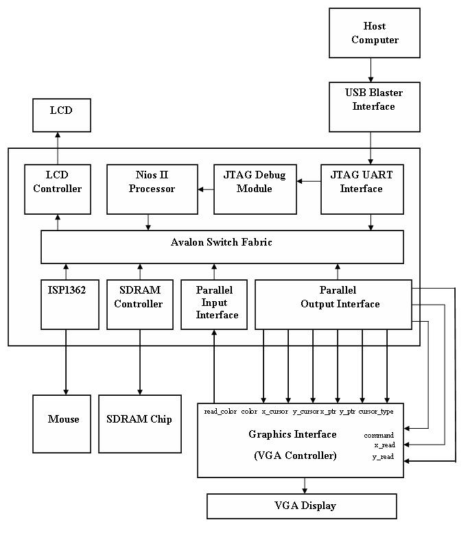
The interface between the hardware and software modules was carried out using the SOPC Builder which is described below: SOPC Builder SOPC Builder is a powerful general-purpose system development tool for creating systems including processors, peripherals, and memories. It enables to define and generate a complete system-on-a-programmable-chip (SOPC) in a substantially less time and automates the task of integrating hardware components into a larger system. In addition to its role as a system generation tool, SOPC Builder provides features to ease writing software and to accelerate system simulation. An SOPC Builder component is a design module that the SOPC Builder recognizes and can automatically integrate into a system. The system components are specified in a GUI and custom components can also be defined and added. SOPC Builder recognizes all these multiple components and automatically integrate them into a system. It connects these multiple components together to create a top-level HDL file called the system module and generates system interconnect fabric that contains logic to manage the connectivity of all components in the system. The main SOPC Builder components which were implemented for interfacing the USB mouse with the Altera DE2 board are as follows: 1) cpu_0 The highest level NIOS II/f “fast” version processor was used to achieve optimal speed levels for interfacing the mouse and reading / writing the pixel values to the VGA as it has the widest scope of configuration options that can be used to optimize the processor for performance. The CPU runs at 100 MHz and performance of the processor at this system frequency is up to 101 DMIPS. It consists of three M4K memory blocks and has 4KB of Instruction Cache and 2KB of Data Cache with a line size of 4 Bytes. 2) sdram_0 The SDRAM is used as memory for the NiosII processor 3) lcd_16207_0 It is used to interface the LCD on the Altera DE2 board with the NIOS processor to send the appropriate commands to control it. 4) ISP1362 It is used to interface the USB mouse on the Altera DE2 board with the NIOS processor to send the appropriate commands to control it and display the mouse cursor on the VGA screen. Communication between NIOS II and FPGA The following wires are used to interface between the C code running on the NIOS II processor and the hardware in FPGA:
Figure1: Interface Block Diagram 1) color [15:0] (output) is used to define the value of color to be displayed at a particular pixel location on the VGA monitor. It consists of the data for two adjacent pixel locations which are differentiated on the basis of the last bit of the x co-ordinate, defining a pair of consecutive even and odd pixel locations. The lower byte contains the data for the odd pixel while the higher byte has the data for the even byte. The 8 bits of data for each pixel is composed of 3 bits each for Red and Blue components and 2 bits for Green component. 2) x_cursor [9:0] (output) specifies the x co-ordinate of the cursor which is sent as an input to the VGA Controller module to display the mouse pointer on the VGA monitor. 3) y_cursor [9:0] (output) specifies the y co-ordinate of the cursor which is sent as an input to the VGA Controller module to display the mouse pointer on the VGA monitor. 4) x_ptr [9:0] (output) is used to define the x component of the addr_reg which, along with the y component, completely determines the position of the respective pixel on the VGA monitor. The higher 9 bits are used for addressing to achieve a resolution as close as possible to 640 pixels in width. 5) y_ptr [9:0] (output) is used to define the y component of the addr_reg which, along with the x component, completely determines the position of the respective pixel on the VGA monitor. The lower 9 bits are used for addressing to achieve a resolution as of 480 pixels in height. 6) command [1:0] (output) flag is used to control the writing to / reading from the VGA monitor. The value of 1 denotes writing the color value to the VGA monitor while a value of 2 denoted the reading of color value from the VGA monitor. 7) cursor_type [7:0] (output) is used to send a signal to the VGA controller module to determine the type of cursor to display on the VGA monitor. The value of 1 for the cursor_type denotes the normal “pointer” type cursor, the value of 2 denotes an “eraser” type cursor of size one, the value of 3 denotes an “eraser” type cursor of size two and the value of 4 denotes an “eraser” type cursor of size three. 8) x_read [9:0] (output) specifies the x co-ordinate of the pixel position on the VGA monitor from where the value of the current color is to be read and is sent to the software module for further processing. 9) y_read [9:0] (output) specifies the y co-ordinate of the pixel position on the VGA monitor from where the value of the current color is to be read and is sent to the software module for further processing. 10) read_color [15:0] (input) takes the value of color that is displayed at a particular pixel location on the VGA monitor given by x_read and y_read values and sent to the software component of the complete system. It reads the data for two adjacent pixel locations which are differentiated on the basis of the last bit of the x co-ordinate, defining a pair of consecutive even and odd pixel locations. The lower byte contains the data for the odd pixel while the higher byte has the data for the even byte. The 8 bits of data for each pixel is composed of 3 bits each for Red and Blue components and 2 bits for Green component.
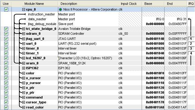
Figure2: SOPC Builder Display
|
|
|