
Communication
Message Format
All messages follow a very specific format. The actual content of the message has a 3 byte header, a 1 byte tail, and a variable length body ranging from 0 to 97 bytes. The message format can be seen below.
![]()
The length field designates the total length of the message after the length byte. So if there were 1 byte of data, the length would be 4 (1 byte for node id, 1 byte for command, 1 byte for data, and 1 byte for stop byte).
The node ID field specifies whom the message is intended for. The PC, master node, and receiver nodes each have a unique ID, and only respond to messages with their own node id’s, with the exception of messages sent from the PC to the master node. These messages are simply transmitted by the master node to the proper receiver node. The single byte allows for up to 120 unique receiver nodes in the network, with 8 reserved ids. Three of these ids are currently used: for the PC, master node, and un-initialized nodes.
The command field contains the message command, telling the given node how to interpret the message. There is room for up to 128 different commands. If necessary, additional bytes in the data field can easily be used to extend the number of commands nearly indefinitely, especially because the data field is directly next to the command field.
The variable length data field can contain nearly anything, from extra command information, to state information, to such things as GUI layout information. Many messages also contain blank data fields, such as a simple on and off command.
Finally the stop byte is simply all 0’s, and designates the end of the message.
Communication Message Format
While the content of the message was described above, additional bytes are prepended to all messages transmitted wirelessly in order to aid successful communication. This extended format can be seen below:
![]()
The 3 hardware start bytes are all 0xAA. Their purpose is to attune the receiver to the specific voltage level of the incoming signal. 0xAA was used for this because alternating 1’s and 0’s guarantees a balanced signal, which the receivers are best at listening to. These start bytes are sent before any message automatically by our network software.
Our network software also adds the frame alignment byte automatically, and is a single byte containing 0xFF. The 8 1’s guarantees that the bytes received after the frame alignment byte are properly aligned. This is necessary because the USART protocol uses a 0 as a start bit, and a 1 as a stop bit for each byte sent. Since the start bytes are 1’s and 0’s, it is possible that if a receiver starts receiving the signal partially through one of the start bytes, it will be misaligned, counting one of the actual bytes within the start byte as a start bit. The frame alignment bit of all 1’s guarantees that one of the 8 1’s is counted as a stop bit if the bytes were misaligned. Since the rest of the byte is 1’s, it is guaranteed to count the next 0 it sees as the start bit of the next byte coming in, which is guaranteed to be the start bit of the next byte sent, guaranteeing frame alignment.
After the frame alignment byte come four more start bytes of 0xaa. These are intended to guarantee that the signal detected is not simply noise, but is actually a message following our protocol, intended to be listened to by receivers on our nodes. These four bytes also help cut through outside noise. All four of these start bytes must be successfully received in order for the software to begin recording the rest of the message. Once they have been received, the software will store all bytes received until a stop byte is received. In addition to helping to cut through noise, requiring all four start bytes to be correctly received also increases the probability that the signal is clean, decreasing the probability that the receiver will record and act upon a message containing errors.
Finally the content bytes were described above. Just as a note, several other checks are performed on the content of the message to insure that it is valid. The node ID must match the node ID of the node receiving the message and the message length field must match the actual length of the message, from message length field to stop byte.
With all of these checks, there is a strong probability that any message accepted by the software for interpretation is actually valid and without errors. Given more time, we would also add parity checking to further guarantee the validity of messages. But even without this, through testing we found that all messages that successfully passed our checks did not contain any errors.
RF Communication
The communication between the master node and the receiving nodes is accomplished through the use of an RF transmitter/receiver pair. The RF parts used will automatically convert the analog signals into digital data and visa versa. This section focuses on how the microcontroller interfaces with the RF components to interpret the data that is transmitted and received over the network.
USART Protocol
The Atmel Mega16 microcontroller that HomeNet uses contains a hardware Universal Synchronous and Asynchronous serial Receiver and Transmitter (USART). The USART is extremely useful because it allows for full duplex serial communication and uses hardware logic to send and receive a full byte of data, which limits the amount of software overhead required. This device fits perfectly into our network framework by providing a convenient method of handling the communication of data across the network and only requiring two pins on the microcontroller.
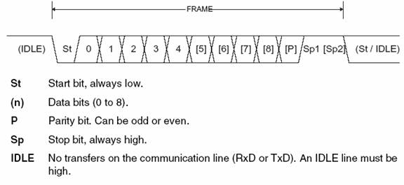
Figure 3 -- USART Communication Protocol[1]
Figure 1 shows the communication protocol that the USART uses to transmit or receive a byte of data. When no data is being communicated, the USART is in the IDLE state – which means that the pin it is transmitting or receiving on is set high (logical 1). As long as the pin remains high, the IDLE state will persist. The beginning of communication is initiated with a single start bit, which is accomplished by setting the pin low (logical 0) for one cycle. After the start bit, the next 8 cycles will consist of the data bits of the byte being communicated and are sent from the least significant to most significant bit. Finally, a stop bit is sent by setting the pin high. This signals the end of the byte communication and also serves as the beginning of the IDLE state (since our implementation does use parity, the parity bit is not included). When sending multiple bytes, the IDLE state can be overlapped with the stop bit so that the pin is high for only a single cycle.
Using the USART
Before using the USART on the Mega16, it is necessary to initialize the baud rate and the interrupts that will be used. The baud rate controls the speed at which the bits are sent/received through the USART and the Mega16 allows for rates approaching 0.5 Mb/s. However, due to the limitations imposed by the RF transmitters/receivers, we run the USART at a rate of 2400 bits/s. The USART is also capable of generating interrupts when it has finished transmitting or receiving a complete byte. This eliminates the need to periodically check to see if the USART has completed the task and allows for a stream of data to be communicated as fast as possible.
In the HomeNet network, all RF communication is done on the same frequency. This single channel communication medium makes a true full duplex implementation impossible. Thus, an individual node will either be transmitting or receiving through the USART, but never both at the same time. Because of this requirement, it is important to ensure that transmit and receive are never active simultaneously. The default state for the node is to have the receive interrupt enabled and the transmit disabled. This allows the node to listen for a message from the master node without accidentally interfering.
In order to overcome the power consumption problem of the transmitters, two options were explored: inverting the data going to and coming from the microcontroller or turning off the transmitter when it is not needed. Placing inverters between the microcontroller, transmitter, and receiver was not a very attractive option because it would require us to find space for even more components in our physical layout of the circuit, so more time was spent devising a method of turning off the transmitters. Initially a PNP transistor was used as a switch on the Vcc being supplied to the transmitter. This solved the power consumption problem for the transmitters, but introduced an additional, unexpected problem.
Upon being turned on, both the RF transmitters and receivers need several milliseconds to get their internal oscillators started and stabilized. This means that after enabling power to flow to the transmitter, the microcontroller must wait several milliseconds before initiating the USART transmission. This hurt our overall network performance by increasing the round trip message latency by 10%. After some experimenting, a better solution was arrived at. It was determined that the output of the USART itself could be shut off. Technically, this violates the USART protocol because the IDLE state is no longer being transmitted, but neither is a Stop Bit (which is also represented by a logical ‘1’). Since the receiver USART never sees a Stop Bit, it will continually disregard the all zero data bytes and no false messages will be allowed. This final software solution allows the nodes to save considerable power when no message is being transmitted, eliminates interference with other nodes by constantly transmitting, and adds no additional latency to message transmission – the perfect solution.