
Software
PC Software
The PC software was written in C++ using Visual Studio .NET 2003. It consists of four major components, each of which has a standard interface through which the other components interact with it. The actual implementation of the individual components could easily be changed without affecting the other components. So, while our implementation of the PC software is fairly simple, it is designed in such a way such that it can be very easily extended to include many more features.
The four components within the program are the GUI, a communication component, a command interpreter, and the data storage and manipulation component. The user interacts with the program through the GUI, which provides graphical objects through which the user can send commands to the various nodes in the network and change various settings. The GUI interacts most directly with the data manipulation component by retrieving objects representing the nodes of the network, and then calling functions through those nodes to send commands to them. The node code then calls functions in the communication component to generate messages for sending, and to actually send messages to the rest of the network. The communication component handles the actual sending and receiving of the messages, and then calls functions in the command interpreter to deal with the acknowledgements it receives from the master node. The command interpreter then updates the data in the data storage component, and the updates are displayed on the GUI.
The GUI, pictured below, is implemented with MFC, using Visual Studio’s class and resource editors. As it is, the GUI provides functionality to send on and off commands to light nodes, as well as to set them to a specific dim level. In addition it allows one to set the com port to communicate over, add nodes to the program via node id, and switch between node ids.
As is usual in GUI’s, our GUI is event based. When the user changes any given GUI component, an event is generated. An event handler is then called to deal with the event. It is within these event handlers that the GUI interacts with the rest of the program by making calls to the other components.
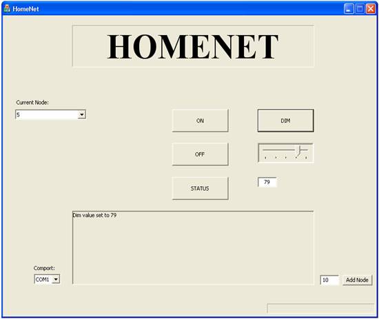
Figure 1 - Screen Capture of the HomeNet GUI
The communication component is designed to interact directly with the com port. Its functionality is actually very limited. The main function it has is a send function, which takes a formatted message, adds the necessary start bytes, and then sends the message over the com port to the master node. It then waits for a response for a limited time before timing out. If it receives a response, it returns the message to the command interpreter, which interprets the message. Communication with the com port is achieved using the windows API, and is done synchronously. It would have been possible to thread the program and perform communication asynchronously, but in terms of a user’s interaction, it did not make sense for the user to be able to do anything after sending a command, until a response is received.
The component is designed to only open a connection with the com port when it is ready to send a message, so the vast majority of the time the com port is not taken up by the program. Because of this, it is obviously not usually listening to the com port, and is unable to receive messages from the master node except after sending a message to it. This is completely by design. More details can be found in the communication section of the report.
The only other functionality this component provides is a function for formatting messages properly. This function takes a destination, command, and any data and formats it properly. This functionality is included in the communication component so everything directly related to communicating with the master node is stored within one component. Since this is so, it would be easy to change protocols, message formats, or even communication devices without affecting the rest of the program.
The command interpreter component has very little functionality at this time since the only commands returned by the master node are simple acknowledgements from light nodes. This component is designed to easily extend functionality to handle any additional responses that nodes will be programmed to make.
Finally the data storage and manipulation component is largely made up of a set of classes representing the different node types. Each node type has its own class set up in a logical inheritance hierarchy. The individual node classes have functionality directly related to that node type. For instance, the light node has a function for setting and storing the dim level of the light. It also inherits from a simple outlet class with on and off functionality. All of the nodes are stored within a node storage class, which holds them in a hash map. Individual nodes can be retrieved from this hash table using the node id of the node being retrieved. The GUI uses the node storage class to retrieve the node it is acting upon, and then is able to call functions on that node.
Microcontroller software
All of the microcontroller software was written using the CodeVisionAVR C compiler, and is in standard C. While the different node types each have slightly different functionality, there is a massive amount of overlap between functionality, especially in the communication portion of the software. Because of this overlap, we decided to write all of the microcontroller code within one project. The majority of the code is stored within one source file because we could not get CodeVision to correctly link multiple source files. There are several headers, including a shared header with many constants that is actually shared between the microcontroller and PC code.
The microcontroller code could be said to be divided into several components, even though they are all within one file. The majority of the code is devoted to the communication component. Within this component there are two parts. The first part is only used by the master node and is devoted to communication with the PC. This part involves a software USART for sending and receiving messages to and from the com port. The second part, which is used by all the microcontroller nodes, is written to communicate between microcontroller nodes via the radio transmitters and receivers using the hardware USART included in the microcontrollers.
The second component would be the message creation and validation component. This component includes functionality for properly formatting messages to be sent to other nodes in the network. It also includes functionality for validating messages received over both the software and hardware USARTs. All microcontroller nodes also share this component, although the receiver nodes only use the hardware USART since they only communicate with the master node through RF.
The final component is the message interpreter. This component is what really differentiates node types. Each node type has a separate function that is called to interpret messages that it receives. All of the functionality of the individual nodes, such as turning on and off lights is embedded in this section of the code.
The entire microcontroller program operates on an infinite while loop. Within this loop a number of functions are called, depending on the current state of the program. A number of poling operations are also performed within this loop. A number of other operations are also performed on an interrupt basis. There are several timers that are running simultaneously, and the USARTS operate using interrupts.
One other general feature that needs mentioning is the msg array. This global array of 100 unsigned characters stores all messages that are received and sent in the microcontroller. We decided to use a single array for this purpose because of the significant memory savings it offers over maintaining several message arrays, and in order to avoid the overhead of passing a pointer to this array around. Maintaining only a single array did present some difficulties. It forced us to be much more careful about receiving and sending messages, as we had to insure that while we were still using the data in the array that it did not get overwritten by a new incoming message, or by other functions using it. Despite these difficulties, we found it a worthwhile design decision.
Dimming/Light control software
The majority of the light controller is accomplished in hardware, so very little software is needed to perform the main functions of the light node: turning on and off, and dimming. In fact, all of these functions are performed with fewer than ten lines of code. The on and off functionality, which can actually be generalized to be for any outlet based control device, simply involves setting a single PIN. Setting this pin to low immediately triggers the triac, allowing current to flow and turning on the light. Setting the pin to high correspondingly stops current and turns off the light.
The dimmer functionality is only slightly more complicated. It basically involves three steps. Within the main program loop, a polling function constantly checks for a zero crossing within the wall power by checking the value of a single pin. When a zero crossing occurs, the wall power is shut off, turning of the light. A timer is then started. Once the timer has run out an interrupt is fired which turns the power back on until the next zero crossing. In this way, the microcontroller controls what percentage of the time the light is on between each zero crossing. This percentage dictates how bright the light appears to the human eye, as it is flickering at a far higher frequency than is perceivable. In order to change the brightness of the light, the delay is simply increased or decreased to dim or brighten the light respectively.
Master Node
The master node’s basic functionality is to act as a relay between the PC and the receiver nodes. Because of this, it has little functionality besides receiving and sending comport messages, and receiving and sending receiver node messages. Any time it receives a PC message it simply sends the message over its transmitter. Any time it receives a message from a receiver node, which it can only do after sending a message to a receiver node, it then sends that message back over the com port to the PC.
The one complication with the master node is the fact that it must communicate over two separate mediums. We initially planned to use the hardware USART for both purposes, but quickly realized that this would not work. The problem is that the receiver pin for the USART is hardwired to both the radio receiver and the com port. The receiver is constantly picking up random noise, so when the USART attempts to receive data over the com port, the receiver causes a conflict, garbling messages. Also, when the PC is not sending any data, it is constantly in the IDLE state and driving the receive pin high which will squash any data the RF receiver may be picking up. In order to alleviate this problem, we decided to implement a software USART using two regular pins instead of the dedicated USART pins.
The software implementation of the USART must precisely match the functionality of the hardware USART since it will be used to communicate with the PC, which expects a specific protocol and functionality. The same byte level receive and transmit functions can be used to interpret and send entire messages, but new code must be written to successfully transmit the individual bits in a byte. The functionality of the software USART is defined in two functions: soft_transmit and soft_receive which are called from a timer interrupt to simulate the hardware USART interrupts.
The soft_transmit is the simpler of the two functions. When it is called, it will set the softTx pin to the value of the Start Bit and on the next call to the least significant bit in the byte to be transmitted. It will then right shift the byte to get rid of the bit just transmitted and advance the next bit to transmit. The next time it is called, the next least significant bit is in the lowest position in the byte and is ready to transmit. This step is repeated for all eight bits in the byte. After the final bit has been transmitted, the soft_transmit function will then send a Stop Bit, enter the IDLE state, and disable further transmission until the next byte to be transmitted is ready to go.
The soft_receive function is more complicated. Since no clock signal is sent along with the data, there is no synchronization between the sender and receiver. This means that the receiver must constantly be sampling the incoming signal to determine what, if anything is being transmitted. After implementing the basic USART protocol on the receiver side, we had problems properly receiving long strings of bytes. This is because the sender and receiver are operating with slightly different clocks and as such the receiver will periodically drop a bit. If even a single bit gets dropped, every byte that follows will be misinterpreted.
To overcome this misinterpretation, we found it necessary for the soft_receive to sample the incoming data multiple times per bit. After some experimenting, we found that sampling each bit at least twice was sufficient. To ensure that every bit was sampled a minimum of two times, the sample rate of the receiver had to be more than doubled compared to the sender. Sampling faster than twice the speed of the sender enabled us to grab every bit being sent without ever dropping any. However, this increased the complexity of the soft_receive function significantly because it was now required to detect patterns of inputs and properly decipher what the appropriate single data bit value was supposed to be. This caused problems during debugging but after we perfected the pattern recognition and timing, the software USART worked perfectly for communicating with the PC.