
Udit Gupta
- • Software : Bluetooth, IR Sensors, RTCC, Motor Control & Robot Following
- • Software Integration
- • Prototype circuits for IR Beacon Anklet and RTCC Oscillator
- • Buying Materials
The robot companion that delivers what you need, when you need it!
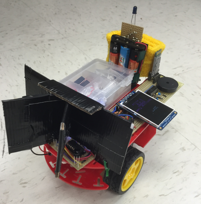
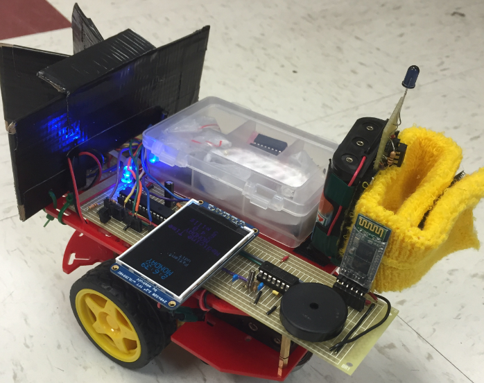 Medi-Bot poses for the camera. Side view.
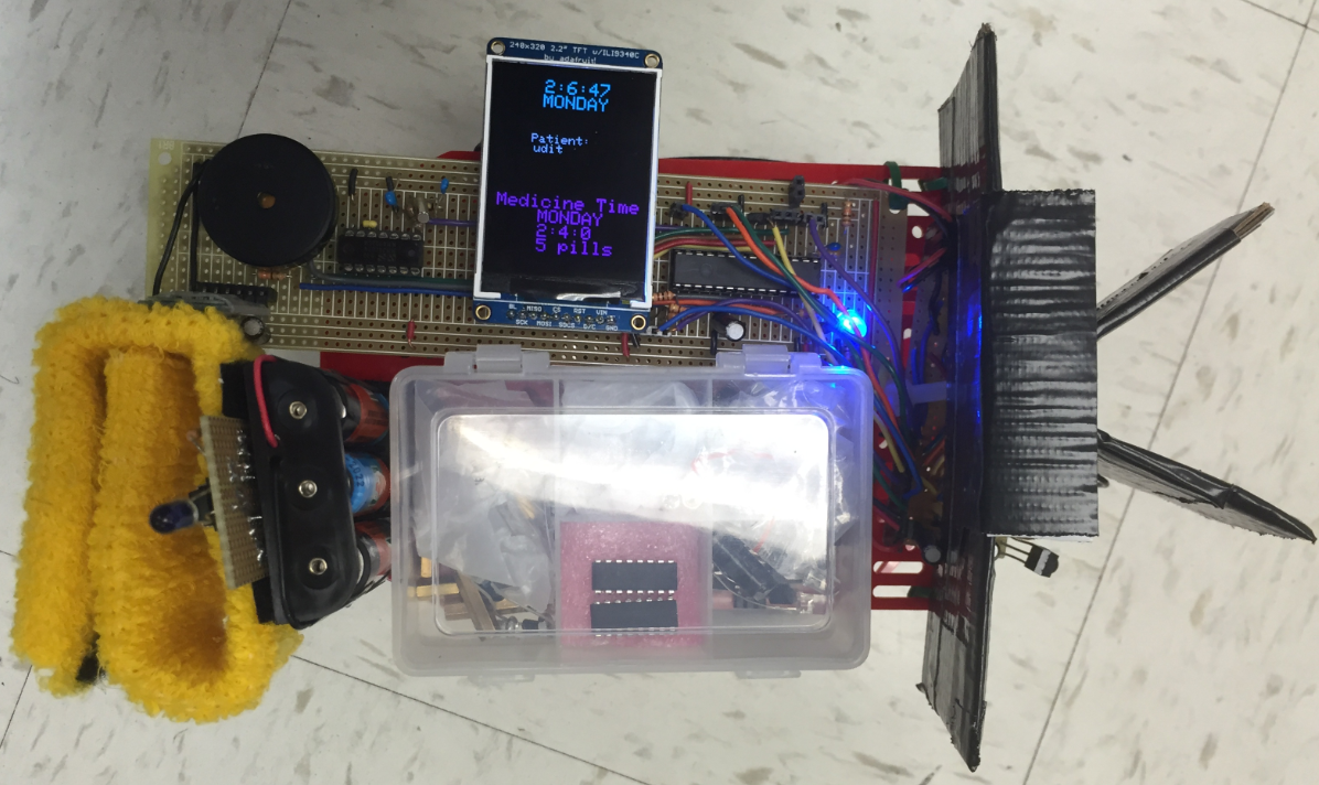 Medi-Bot poses for the camera. Aerial view.
 Medi-Bot poses for the camera. Front view.
For our final project, we implemented a robot car called Medi-Bot that will deliver the things you need, when you need them. In our case, we illustrate the proof of concept of our project in personal medical care. Whereas many medical devices focus on large-scale medical procedures (i.e, surgery, therapy, etc.), we wanted to implement a device that could be used in a variety of settings to have a more personal emphasis. Our product allows the user to have ease of communication with Medi-Bot as well as flexibility over Medi-Bot's personalization options.
The main mode of communication between user and Medi-Bot will be through a Bluetooth Terminal application on an Android or Windows cell phone. In addition to the Bluetooth Terminal application, users will carry an additional IR pulser board integrated into a wearable anklet for easy portability. This board will continuously send out 56 kHz pulses so that Medi-Bot will be able to identify and locate the user.
When Medi-Bot is initially turned on, it will prompt the user to input all the times he or she need to take medicine in a week. Medi-Bot will then store this information and notify you when it comes time to take your medicine. Medi-Bot will sound a buzzer, send a Bluetooth notification, and prompt the user either to enable RC drive mode or to allow the car to follow the user autonomously. In following mode, the car follows the user around. Future iterations of this project will allow for the robot to navigate around a room and autonomously find the user, mitigating the dependency on RC drive mode and facilitating usage.
One of the ideas that came up during our discussion of possible final projects was the Runaway Clock. Inspired by the idea of time and movement, we then started discussing the idea of a small car that could deliver medicine or first-aid to elderly patients when they need it. We realized, though, that the combination of room navigation and user identification would be quite difficult to implement, so we simplified it into a car that would either follow or be user-controlled to give the medicines. This later resulted in Medi-Bot, the personal medicine botler.
Medi-Bot User Model
The Medi-Bot user model can be partitioned into two main actors - the user and Medi-Bot itself. The user communicates with Medi-Bot using bluetooth via a cellphone. This commmunication allows the user to configure Medi-Bot (e.g. current time and scheduling medicines) and control Medi-Bot (e.g. RC drive mode). Medi-Bot carries a bluetooth module as well to enable the two-way communication with the user.
The user can also use an optional wearable anklet which functions as an IR beacon. The beacon emits IR pulses which can be detected by the IR sensors on Medi-Bot. These are used for Medi-Bot to track and follow the user. Additionally, Medi-Bot hosts an RTCC oscillator for high precision time tracking, a piezo-buzzer to indicate when medicine should be taken, and motor controllers to operate the robotic car itself.
Medi-Bot System FSM
Medi-Bot has two modes of operation: INITIALIZATION and RUNNING. All initialization states are colored in green and all running states are colored in blue in the above diagram.
The initialization states start with the RESET state. This is the state of the machine when it is initially powered on. The system then transitions to the ENTER NAME state where the user enters their name. This is followed by the CURRENT TIME state where the user can enter the current day and time. The corresponding prompt on the user's bluetooth is shown below. The time is maintained by a high precision hardware-based RTCC on the PIC32 with an external oscillator.
"Current Time? (DAY HR MIN SEC)"After entering the current time the user can then enter an arbitrary number of medicines to be taken regularly each week. Medi-Bot also keeps track of the quantity of each medicine to take. The user's bluetooth prompt is shown below.
"Medicine Schedule? (DAY HR MIN QUANTITY)"After "done" is typed on the bluetooth terminal, the system transitions into the FOLLOWING MODE state. In this state, Medi-Bot follows the user. If Medi-Bot cannot track the user it will spin in place for approximately 10 seconds looking for the user. After the allotted search time Medi-Bot automatically transitions into RC Drive Car mode. The user can command the car to go "fwd", "rev", "right" and "left" for a specific amount of time and a given PWM value for each wheel. The PWM values are mainly used to calibrate the speed of the car. The user's bluetooth prompt in RC drive mode is provided below. The user can transition Medi-Bot back to FOLLOWING MODE if they type "follow".
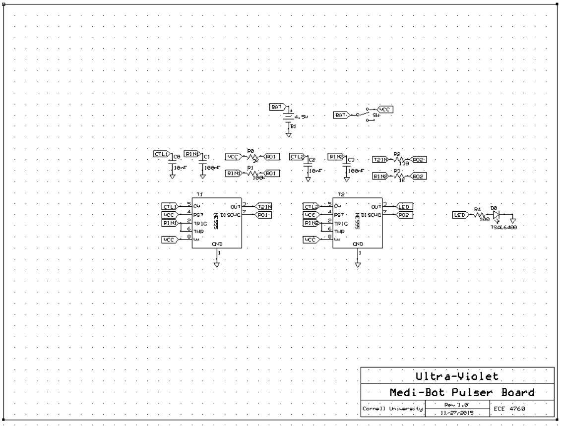
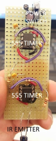
"Drive Car? (DIR Time(ms) PWM_right PWM_left)"The only component that required background math is the pulser circuit for the IR emitter. The IR emitter needs to emit 56 kHz bursts in order for Medi-Bot's following mode to work. Thus, we needed to construct a circuit that was able to produce these bursts. We referenced this site and used two 555 timers to implement this circuit. The first timer produced a waveform of about 700 Hz, which modulated the output of the second timer, a timer circuit simply outputting a 56 kHz square wave. In order to specify these two timer circuits to produce 700 Hz and 56 kHz, we needed to do some math to come up with approximate resistor and capacitor values. To get these values, we used the following equation:

There were several hardware and software tradeoffs. The main tradeoffs involved:
Large Vs. Small Chassis
Originally we wanted to use a larger chassis for Medi-Bot mainly because it looked sleeker and had much more room to hold a larger medicine box and additional first-aid supplies. The problem with the larger chassis, though, was that its four motors required more pins used up on the PIC32 and more H-bridge motor drivers. Plus, it would also be more difficult to control the car overall, especially for turning. Hence, we decided to go with the smaller chassis in the end as it only had two motors with only one H-bridge motor driver and was more cost-effective and easier to control compared to the larger chassis.
LED Decoder Vs. TFT Display
One of the earlier ideas we considered was to place LEDs in each compartment of the medicine box. Depending on the day, the corresponding LED would light up to identify which compartment the user needed to open to eat their medicines. To do this, we needed seven LEDs and therefore would need a 3 to 8 line decoder. Once we obtained the decoders and started assembling the car, we realized that we would like to keep the TFT display for ease of debugging. Unfortunately, the PIC32 did not have enough pins to use for the H-bridge motor driver, the three IR receivers, the buzzer, the Bluetooth HC-05 module, the RTCC, the LED decoder, and the TFT display. Thus we decided to sacrifice the LED decoder in favor of keeping the more pragmatic TFT display.
Hardware Vs. Software Pulser
When using the IR emitter and receiver combination, the emitter needs to be able to send 56 kHz bursts. There were two ways for us to do this. The simplest way would be to use another microcontroller and program it to send 56 kHz bursts through the IR emitter. We thought that this would not be an effective use of our budget, and thus we attempted to send the 56 kHz by constructing our own hardware pulser circuit based on online resources. We successfully implemented a hardware pulser that was more cost-effective compared to the software pulser.
Ultrasonic Transducers Vs. IR Emitters and Receivers
As mentioned earlier, the combination of room navigation and user identification would have been too difficult for the amount of time allotted. Thus, we designed our car to constantly follow its user. During the initial planning stages, we saw that previous people had created human-following robots using ultrasonic transducers. These ultrasonic transducers give about a range of 5m between the user and the car. After consulting Bruce, we realized that the ultrasonic beacons and receivers might be more complex than necessary and we thus opted to use his suggestion of a standard IR emitter and IR receivers. This turned out well because the ultrasonic beacons and receivers were actually very expensive and would have consumed a large portion of our budget. On the other hand, the IR emitter and receivers cost very little in comparison to the ultrasonic beacons and receivers. One con with switching, though, was that our tracking range was reduced from 5 to 1.5m.
The main IEEE communication standard we used for the project was IEEE 802.15.1, Bluetooth (Wireless personal area network)
We also adhered to the IEEE code of ethics which states that professionals must commit themselves to the highest ethical and professional conduct. Some key tenants of the code of ethics that played a role in our projects included being "honest and realistic in stating claims or estimates based on available data". This played a role in reporting results we found regarding the Bluetooth module and sharing our experience with the real-time oscillator. We did not accept bribery in any form. We always tried to "improve the understanding of technology" as seen in our efforts to develop the RTCC module for the PIC32 sytsem as well as report errors we encountered with the Bluetooth HC-05 module. We also "assist[ed] colleagues and co-workers in their professional development" by once again sharing our experience with the RTCC, Bluetooth and IR systems. We hope to make available this information so that future projects will also benefit from our efforts.
As Medi-Bot may one day strive to become a commercial product, we would have to also adhere to ISO 13482:2014 which outlines some specifications for robots, especially ones that provide medical care or act as medical devices. The standard mainly addresses safety concerns for robots that interface directly with humans.
Surprisingly we could not find many patents, copyrights and trademarks on personalized medicine robots like Medi-Bot. Many personalized medical robots are much more elaborate and focus on automating specific, complex medical procedures. More simple, everyday use-case personal robots are not as prevalent to the best of our knowledge. That being said there are a few robots targeting hospitals that are similar in function to Medi-Bot, such as the Swisslog RoboCourier which dispatches specimens, medications and supplies throughout hospitals. Similarly, TUGs also dispatch medication, linens and food across hospitals. Medi-Bot differs from these previous efforts in that it aims to offer an economical, small scale solution to personalized medical care as opposed to more expensive, complex industrial scale applications in hospitals.
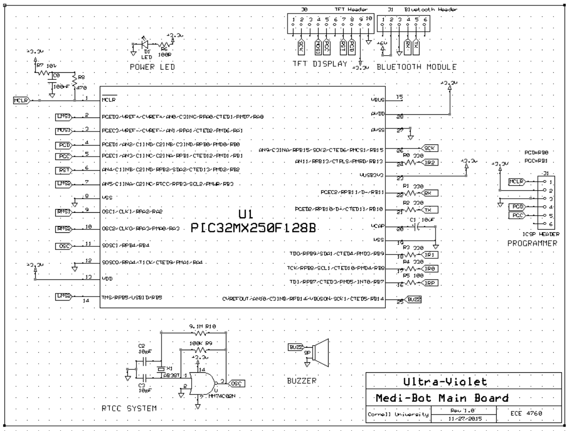
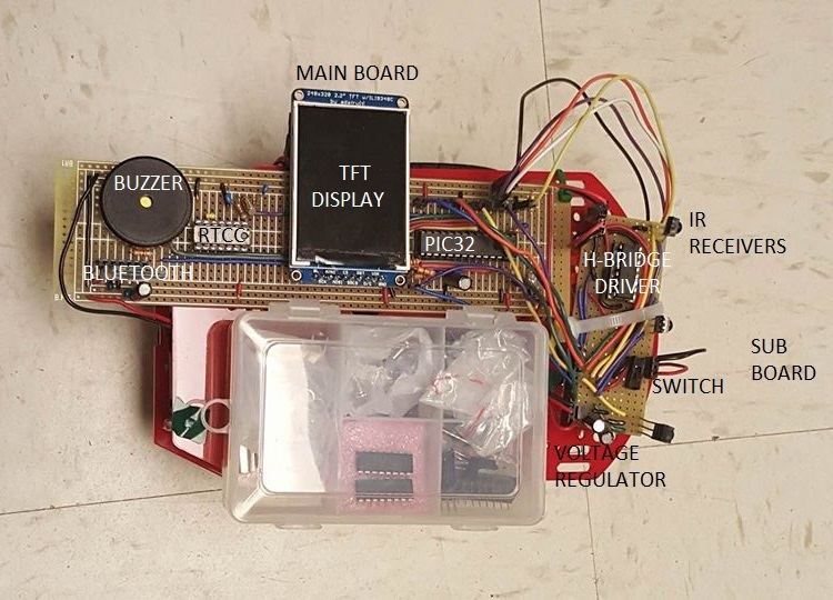
Medi-Bot is composed of several different subsystems. The larger subsystems involved the Realtime Clock and Calendar system, the Bluetooth communication, motor control, and the IR emitter and receiver circuitry used to follow the user. Other smaller components include the buzzer, the TFT display, the voltage regulator circuit, and the standalone PIC32 microcontroller.
For the circuitry, we divided it into three circuit boards:
The Realtime Clock and Calendar System is used to set the alarm times of the medicines as well as keep track of the current time and day.
Hardware Design
The heart of the RTCC hardware lies in the 32 kHz crystal oscillator used to keep time. Details of the circuit are shown in the main board schematic in the Appendix. Along with 10 pF capacitors connected to either terminal of the crystal to ground, we also use a logic NOR gate to achieve an output that looks more like a square wave as opposed to a sinusoid. One of the two inputs to the gate is grounded, and the other is a terminal of the oscillator. 100 kΩ and 9.1 MΩ resistors connect each terminal of the oscillator to the output of the NOR gate. The output is then fed back into the PIC32 as an input on the SOSCI pin.
Software Design
The Software for the RTCC is separated into two main components: initial configuration and run-time configuration. Initial configuration is achieved using plib functions, as seen below. The initialization function is placed in main to be run at startup.
void rtcc_init(void) {
    RtccInit();
    while (RtccGetClkStat() != RTCC_CLK_ON); // wait for SOSC - should not wait for 32ms
}
typedef struct {
    days_t day;
    int hour;
    int minute;
    int quantity;
} med_t;
void rtcc_set_time(void) {
    tm1.l = RtccGetTime();
    tm1.hour = (char) int2bcd(curr_hour);
    tm1.min = (char) int2bcd(curr_min);
    tm1.sec = (char) int2bcd(curr_sec);
    RtccSetTime(tm1.l);
}
void rtcc_set_alarm(void) {
    RtccGetTimeDate(& current_rtcc_time, & current_rtcc_date);
    current_rtcc_date.wday = int2bcd(meds[current_medicine].day);
    current_rtcc_time.hour = int2bcd(meds[current_medicine].hour);
    current_rtcc_time.min = int2bcd(meds[current_medicine].minute);
    RtccChimeDisable();							// don't want rollover
    RtccSetAlarmRptCount(0);					// one alarm will do
    RtccSetAlarmRpt(RTCC_RPT_WEEK);			// enable repeat rate, check the second field
    RtccSetAlarmTimeDate(current_rtcc_time.l, current_rtcc_date.l);		// set the alarm time
    RtccAlarmEnable();							// enable the alarm
}
Bluetooth is used as the main communication scheme between the user's phone and Medi-Bot.
Hardware Design
Connecting the HC-05 Bluetooth Module to the PIC32 was fairly simple. There were four pins we needed to connnect: VCC, GND, TX, and RX. For power, we used a 6V supply and bypass capacitors. We also connected TX and RX with 330 Ω resistors to the RX and TX pins of the PIC32.
Software Design
To communicate with Medi-Bot, the user needs to have an Android phone where they can download the Bluetooth Terminal application. To setup the bluetooth HC-05 module we referenced Shela Wang and Christine Soong's wireless robot project from the previous year. The instructions are the same so we decided not to copy the procedure again and developers should reference the link provided. Once the HC-05 is setup with the PIC32 you can now use the bluetooth terminal application to talk to the HC-05 module. First, Append newline(\r\n) needs to be selected and saved in the setup before any messages can be sent to the robot. The user then can connect with the robot by selecting Connect a device-Insecure->H-C-2010-06-01 20:15:07:24:15:49. The robot will then respond to the user asking for their name, the current time, and their medicine times and quantities. When the user is done typing all their medicines, the car will transfer into following mode and proceed to follow the user.
Testing
Interestingly we noticed that the Bluetooth HC-05 module would often times send malformed bytes that would crash the UART code on the PIC32 (using the provided protothreads library). We could not figure out exactly what caused this problem but we did find a work-around. In the UART code we modify code as follows:
int errored_out = 0;
int PT_GetSerialBuffer(struct pt *pt)
{
    static char character;
    // mark the beginnning of the input thread
    PT_BEGIN(pt);
    num_char = 0;
    //memset(term_buffer, 0, max_chars);
    while(num_char < max_chars)
    {
        // get the character
        // yield until there is a valid character so that other
        // threads can execute
        PT_YIELD_UNTIL(pt, UARTReceivedDataIsAvailable(UART2) || ( UART2GetErrors() ));

        if ( UART2GetErrors() ) {
            UART2ClearAllErrors();
            num_char = max_chars;
            errored_out = 1;
        } else {
            errored_out = 0;
        // REST OF PT_GetSerialBuffer() code here...
}
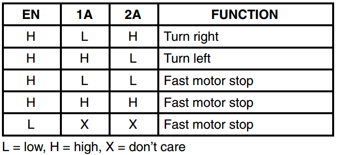
For Medi-Bot, we wanted to be able to control the robot to go forward, left, and right and therefore needed to add some circuitry to control the direction and speed of the motors.
Hardware Design
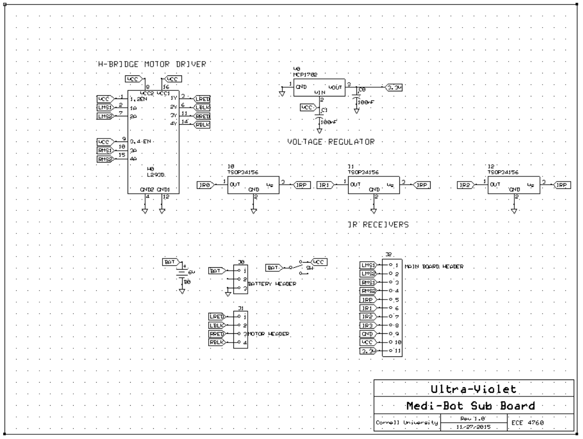
To control the motors, we used a L293D dual motor driver that could take in PWM input to drive the speed and direction of both the left and right motors. The L293D typically takes in 6 inputs from a microcontroller, but we tied the 1,2EN and 3,4EN pins to VCC so that we could save the number of pins used on the PIC32. For motor direction, we followed the datasheet specification table shown below:
void FWD_LEFT_WHEEL(int pwm_control_l) {
    SetDCOC1PWM(pwm_control_l);
    SetDCOC2PWM(0);
}
void REV_LEFT_WHEEL(int pwm_control_l) {
    SetDCOC1PWM(0);
    SetDCOC2PWM(pwm_control_l);
}
void FWD_RIGHT_WHEEL(int pwm_control) {
    SetDCOC4PWM(pwm_control);
    SetDCOC3PWM(0);
}
void REV_RIGHT_WHEEL(int pwm_control) {
    SetDCOC4PWM(0);
    SetDCOC3PWM(pwm_control);
}
void OFF_LEFT_WHEEL(void) {
    SetDCOC1PWM(0);
    SetDCOC2PWM(0);
}
void OFF_RIGHT_WHEEL(void) {
    SetDCOC4PWM(0);
    SetDCOC3PWM(0);
}
In order for Medi-Bot to accurately detect the presence of its owner and follow him around, we decided on using IR emitter and receiver circuits. The IR emitter circuit is incorporated into an anklet to be worn by Medi-Bot's owner, and IR receiver circuits are attached to the front of Medi-Bot's frame.
Hardware Design
As shown in Figure B2 above, the IR emitter circuit consists of two separate 555 timer circuits that have been cascaded together. The first IR emitter circuit has component values selected to configure the pulsing time to be a reasonably low frequency of around 140 Hz. The output of the first timer circuit is used as the power source for the second 555 timer circuit, which is configured to have a much higher pulsing frequency of 56 kHz. Thus, the output waveform of the second 555 timer circuit looks like 56 kHz bursts. The output of the second 555 timer circuit is then fed into the IR emitter, which will generate bursts of IR radiation at 56 kHz.
The IR receiver circuit simply consists of the IR receiver, with the GND pin connected accordingly, the power line connected to a common output pin from the PIC32, and the signal line fed back into the PIC32 as an input. We use three total IR sensor circuits to aid in the directionality of the robot's movement: a left sensor, a middle sensor, and a right sensor. We also shield each of the IR sensors from one another, thus making it easier to distinguish the position of the robot relative to the human through software.
Software Design
In software, we continually poll each of the three IR sensors sequentially, reading the center IR sensor first, then the left sensor, then the right sensor. That is, every 25 milliseconds or so we check to see whether an input capture ISR has seen pulses from the IR receivers (3 input capture units for 3 IR sensors). The number of pulses are reset every 25 milliseconds as well. So long as the front sensor sees the IR radiation from the emitter circuit, Medi-Bot will prioritize forward movement and call rc_drive_car("fwd") continually until IR radiation is no longer detected on the front sensor. Once IR radiation is detected solely on the left or right ride of the robot, Medi-Bot turns toward either direction accordingly by calling rc_drive_car("right") or rc_drive_car("left") until the front sensor once again detects the IR radiation. Note also that due to the nature of the IR sensors, we must also manually power cycle the IR sensors in software by toggling the power line quickly every 100 milliseconds or so. The IR sensors we use do not automatically continue searching for IR radiation once the radiation is lost.
If Medi-Bot is unable to detect IR radiation on any one of the three IR sensors, he will proceed to revolve in a circle for 5 seconds, attemping to relocate the human. Once 5 seconds have passed and Medi-Bot has unsuccessfully detected any IR radiation, he will default to RC driving mode and will not continue attempting to follow the human. At this point, it is the human's responsibility to manually drive Medi-Bot to be within range again and manually put him back into following mode by using the Bluetooth terminal.
Testing
Initially, we started out with a different IR emitter circuit and soon came to realize that although the breadboarded version of the circuit worked well, the soldered version of the same circuit on the perfboard ceased to work. The 555 timer chips are particularly sensitive to the presence of capacitances, and we figured that a circuit that could work given the added parasitic capacitances of the whiteboard but wouldn't work on a standard perfboard could not be a reliable option for our project anyhow. The second circuit we use, as shown in Figure B2 and Pulser Board Schematic in the Appendix, translates identically from the breadboarded version to the perfboard.
The following code that our robot abides by is fairly simple and straightforward; the difficulty of integrating the hardware and software together came from figuring out how best to shield each IR sensor from one another. We tried many different shielding mechanisms but eventually settled on using stiff cardboard covered with black tape arranged in a "K" shape to block the sides of the sensors as well as the back of the sensors.
Along with our important subsystems detailed above, we incorporated several other pieces of hardware which aided in the overall functionality of our Medi-Bot.
TFT Display
The TFT Display on our project serves several purposes: for the most part, we used it to aid in debugging our project throughout the course of its development. In the end, however, it functions as a user interface. Important details such as the user's name, the date and time, and medicines to be taken are printed to the TFT screen. The TFT display uses 5 pins of the microcontroller for the SCK, MOSI, CS, RST, and D/C lines.
Buzzer
We incorporated the usage of a buzzer in order to sound an alarm once the medicine is to be taken by the user. The buzzer circuit is very simplistic; it is driven by toggling an output pin on the PIC32 at a certain frequency to generate a square wave, which is fed into one pin of the buzzer. The other pin is grounded. We configure this buzzer to sound five times once it is time for the user to take his medicine.
Standalone PIC32 Microcontroller
We use the PIC32 microcontroller as a standalone component in our final circuitry, instead of associating the microstick with it in order to program the chip. We choose to do this to further cut down our budget. Thus, we also necessarily use the PICkit3 as a tool to program the chip. Details on how to migrate the PIC32 chip from the microstick onto a breadboard or perfboard are found here and here.
Voltage Regulator
As we have several hardware components that require a 6 V supply and other components that can only tolerate a 3.3 V supply, we incorporate the usage of a voltage regulator in order to necessitate only one voltage supply. We obtain our 6 V supply by putting four 1.5 AA batteries in series, and this supply directly drives the Bluetooth module and the H-bridge motor driver of the robot. Other components of our project, such as the PIC32 chip itself, the TFT display, and the RTCC module operate off a 3.3 V supply which is provided by the voltage regulator (MCP1702) circuit.
Range of IR
The final iteration of Medi-Bot can reliably follow the human at distances of up to a meter before being unable to detect the IR pulses coming from the IR emitter. Realistically, for a more robust product, we would like to extend this range even farther -- perhaps to be on the order of several meters. This distance can easily be extended by replacing the 100 Ω resistor on the IR emitter circuit with one that has a lower value. Since the ability of the IR sensors to detect the IR pulses is dependent on the strength of the IR radiation, we can theoretically extend our range of following simply by increasing the power of the IR pulses. This is done by lowering the resistance value, thus increasing the output current value of the emitter circuit.
RTCC Accuracy
The reason we chose to use an external oscillator instead of the on-chip internal oscillator is due to the fact that we could ostensibly achieve better timing accuracy with an off-chip crystal. As a testament to this assertion, we note that the internal oscillator of the PIC32 is guaranteed an accuracy of 1%. With the external oscillator circuit, the RTCC demonstrates an accuracy of ~0.01% (timing accuracy measurement performed by Sam Miller and Craig Andres in the RGB Matrix Clock project), which translates to about 10 seconds/day. Given the somewhat time-sensitive nature of our project, this accuracy is reasonable.
Following Mode Robustness
We found that polling the IR sensors for input every 25 milliseconds allowed for the robot to more easily detect turns by the human. A longer yield time, such as 100 milliseconds, reduces the update overhead but also reduces the smoothness of the robot's motion, which can contribute to erratic movements resulting in less robust following capability.
Range of Bluetooth
We found the range of the bluetooth module to be adequate for the project. We could send and receive messages reliably at tens of feet (between different rooms) without any problem. We did not do rigorous distance testing for this project because we didn't feel that it was warranted given the use model however we do expect the bluetooth module to work at 100 feet (maybe even more).
Reliability of Bluetooth
Generally the Bluetooth worked well. We did notice a number of instances that the bluetooth HC-05 module would send malformed packets to the PIC32 causing the UART system to crash on the PIC32. We resolved this earlier (reference Bluetooth section) by checking to see if erorrs were raised and appropriately clearing the UART errors followed by terminating the serial process. This worked really well for us!
Medi-Bot is rather small and not that fast. Thus, we do not anticipate it injuring humans or destroying property. However, the onus is on the user to inform the people around him that he uses Medi-Bot so that others are aware of Medi-Bot's presence. We do make the car safer by implementing the RC drive mode so that the user has more control and is responsible for the actions of the robot. For the following mode, the car needs to be in close range to the user so the user himself can warn unaware passerbys not to run into the car.
With regards to the wearable anklet, we would like to assert that the circuitry is simple so that it does not consume too much power and does not overheat. Thus, we do not anticipate the wearable causing discomfort to the user. None of the circuitry is in direct contact with the human, so we also do not anticipate injuries from electrical shocks.
We do use Bluetooth, which sends signals through the air from phone to car. We only attempt to connect to our car only, though and not other people's projects. Because Bluetooth uses frequency hopping, the actual connection between car and phone should not interfere with other people's designs. On another note, if other people require microphones, there is a possibility that our buzzer and motors may cause unwanted noise into their microphone input.
Most people of all ages and needs should be able to utilize our car. Although we recommend that the pulser should be worn near the ankle, the user could also hold the pulser or attach it to something such as a walking stick or somewhere on their chair. As long as it is close to the ground so that the car can see it, it does not matter too much what it is attached to. However, people who do not know English may need some additional instruction to teach them how to use the car initially.
Overall, we have successfully demonstrated what we have originally proposed: a medicine-delivering robot that keeps track of the times the user needs to take their medicine and can either follow the user around or be manually controlled like an RC car. Our final project has many different subsystems that were integrated together, contributing to its complexity. Medi-Bot is the ideal companion for the elderly, the forgetful, and really anyone who would like a medicine-delivering robot!
In the future, we hope to make several improvements to Medi-Bot to achieve more functionality and robustness. Firstly, we aim to replace the simplistic IR receiver circuits with a detection system that could provide a more reliable notion of directionality. Whereas the shields between the IR sensors worked reasonably well, the shields were large and looked rather unwieldy on Medi-Bot's small frame.
Currently, Medi-Bot can only follow a human closely, and once out of range the human must direct Medi-Bot to be within range of the IR beacon once more, treating Medi-Bot as a standard RC car. We hope to append distance sensors to Medi-Bot's frame as well so that, if out of range, Medi-Bot can enter a search mode in order to move around the room autonomously to try and relocate the human itself. This functionality requires the usage of distance sensors so that Medi-Bot does not have to only travel in beeline paths and can navigate around corners and objects (which is much more preferable).
In the future, we also hope to develop our own phone application instead of using a rudimentary Bluetooth terminal. This phone application would be compatible with a variety of phone operating systems and would provide a cleaner, more intuitive user interface for collecting user data. Another additional feature, given this phone app, could be sending notifications to the user's doctor over wifi to notify the doctor when the patient has taken his medicine.
One other useful improvement, which would add much more complexity to the project, would be to allow control over Medi-Bot to happen via brain waves. Ostensibly, we could use electrodes to record the user's neural signals, use low-noise amplification circuits to amplify these brain signals, and process them via software to interpret the signals as commands. In this manner, Medi-Bot would also be able to respond to emergency situations and be much easier to control.
As previously mentioned Medi-Bot follows the IEEE 802.15.1 Wireless Personal Area Network standard for Bluetooth, IEEE Code of Ethics, and the ISO 13482:2014 standard for robotic machinery.
To the best of our knowledge there are no patents, copyrights or trademarks on personalized medicine robots such as Medi-Bot. Because of this we are considering pursuing IP certificiation (e.g. patent) based on future work.
As Medi-Bot combines robotics with human medical care there are a number of ethical implicaitons of the device. First, as we mentioned previously the ISO 13482:2014 outlines a set of guidelines for safety concerning robotic machinery that interacts with humans. The safety of humans is definitely an ethical concern and who is liable if someone is hurt. Another ethical concern is what if a user becomes so dependent on Medi-Bot that they cannot remember their medications otherwise. If in this case Medi-Bot malfunctions (or maybe something less severe like losing power), is Medi-Bot "responsible" for the patient missing medications. We must also considering security concerns of a patient's medical history being more available to others as Medi-Bot does not currently provide any security measures. Finally, certain medication may also need to be kept in specific climates or environments that patients are unaware of. Medi-Bot does not currently offer facilities for such medications. All of these concerns center on the question of the acting agent responsible for Medi-Bot. Is it the user? Developer? Distributor?
There are no legal considerations for our project. HC-05, the Bluetooth module we use, is regulated by FCC standards.
We would like to thank Professor Bruce Land for his invaluable help, support, and patience throughout the development of this project. Additionally, we would like to thank the lab TAs for helping us out and keeping the lab open.
Below is a list of all the major files we used and modified for our project.
| Part | Vendor | Part Number | Unit Price | Quantity | Total Cost per Part |
|---|---|---|---|---|---|
| Chassis, Motor, & Wheels | Karlsson Robotics | ROB-12866 | 20.00 | 1 | 20.00 |
| Batteries | Amazon | N/A | 0.27 | 7 | 1.89 |
| Velcro | Amazon | N/A | 1.00 | 1 | 1.00 |
| Box | Borrowed | N/A | 0.00 | 1 | 0.00 |
| Buzzer | Borrowed | N/A | 0.00 | 1 | 0.00 |
| Real-Time Clock and Calendar (AB38T) | Digi-Key | 535-9034-ND | 0.17 | 1 | 0.17 |
| Microcontroller (PIC32MX250F128B) | Borrowed | N/A | 5.00 | 1 | 5.00 |
| TFT LCD | Borrowed | N/A | 10.00 | 1 | 10.00 |
| Small Solder Boards | Borrowed | N/A | 1.00 | 2 | 2.00 |
| Large Solder Board | Borrowed | N/A | 2.50 | 1 | 2.50 |
| IR Receiver (TSOP34156) | Digi-Key | TSOP34156-ND | 1.33 | 3 | 3.99 |
| IR Emitter (TSAL6400) | Digi-Key | 751-1205-ND | 0.57 | 1 | 0.57 |
| Quad 2-Input NOR Gate (MM64C02N) | Borrowed | N/A | 0 | 1 | 0 |
| Dual H-Bridge Motor Driver (L293D) | Digi-Key | 497-2936-5-ND | 3.90 | 1 | 3.90 |
| Timers (NE555) | Digi-Key | 296-1411-5-ND | 0.44 | 2 | 0.88 |
| Voltage Regulator (MCP1702) | Digi-Key | MCP1702-3302E/TO-ND | 0.48 | 1 | 0.48 |
| Bluetooth Serial Module (HC-05) | e-Bay | N/A | 4.00 | 1 | 4.00 |
| Chip Sockets/Headers | Borrowed | N/A | 0.05 | 133 | 6.65 |
| Jumper Cables | Borrowed | N/A | 0.20 | 4 | 0.80 |
| Total Cost | 63.83 |