ACA: AEP's Can Do Anything
A Two-Degree-Of-Freedom Ball Balancing PID Controller
Gregory Hideo Kaiser & Samuel Oscar Feibel
ghk48 & sof23 - ECE 4760 - Fall 2019
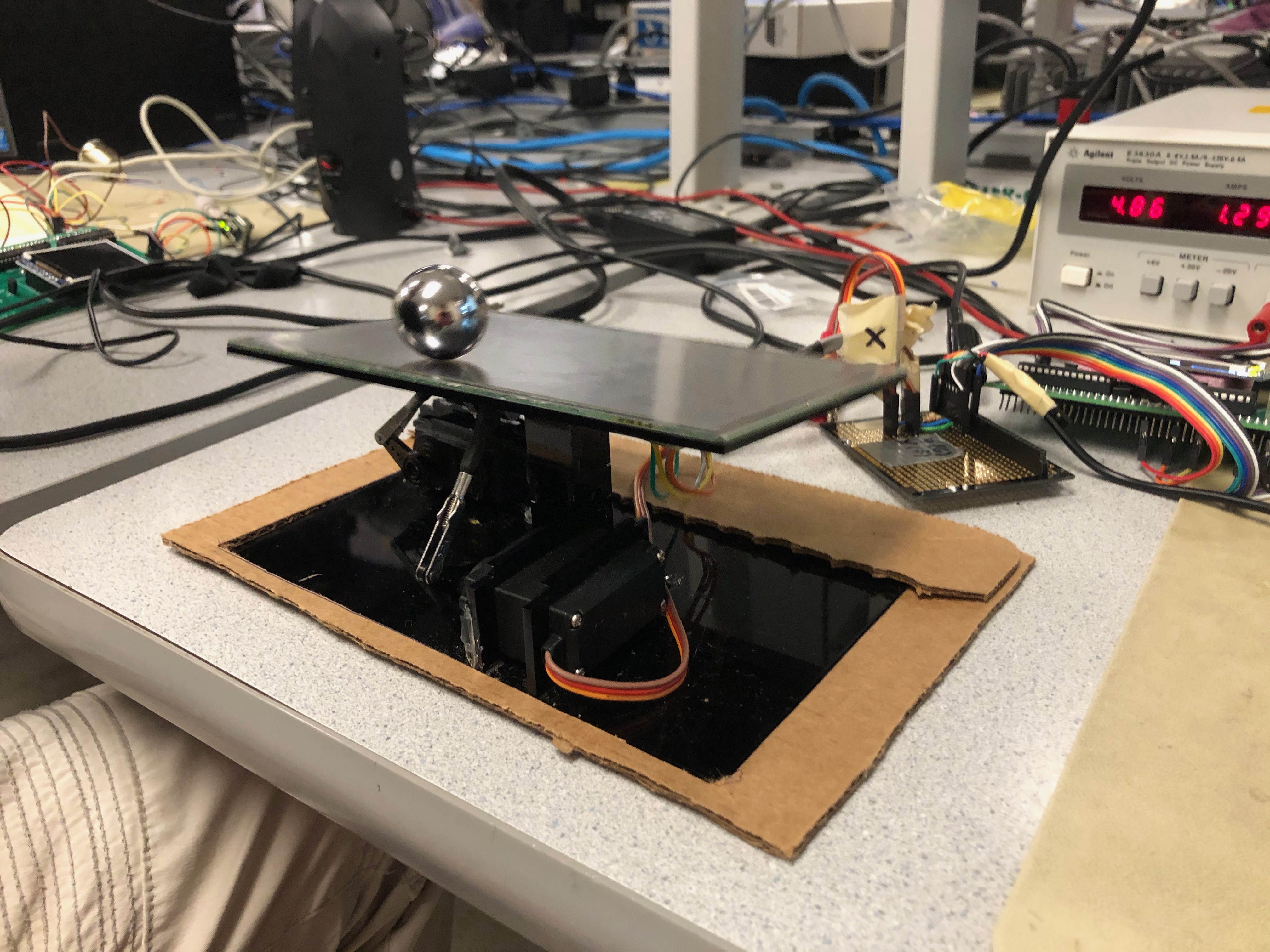
In this project, we implemented a two-degree-of-freedom ball balancing platform using a resistive touchscreen, two servo motors, and PID control.
We used a PIC32 microcontroller to read position data from the touchscreen and drive the servos, adjusting the platform’s angle. We tuned the system to balance a 1 inch diameter steel ball using a PID algorithm. The screen mount was made from acrylic with one 3D printed connection for quick and easy manufacturing. We bought the largest resistive touch screen available for our budget which was a 7x4 inch 4-pin resistive touchscreen from Adafruit to use as our control surface. Using position data from the touchscreen, the microcontroller was able to control the platform position to stabilize the ball through the servos. By isolating the x and y directions, we were able to successfully balance the steel ball on the surface.
The purpose of this project was to utilize our interest and background in fundamental physics and control law in order to implement a system which stabilizes an inherently unstable system. The system we chose was ball balancing on a flat plate. A perfect model of this system is stable, though not asymptotically, but becomes unstable once you account for the minor slop in the joints. This causes the weight of the ball to tilt the platform and accelerate off. We were inspired by a number of youtube videos displaying very similar projects. [1]
Starting from the fundamental physics, assuming the no-slip condition, we derived a relationship between acceleration and angle. While this involves a number of approximations, this derivation could be returned to for more detailed analysis.
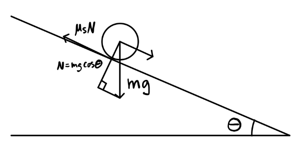
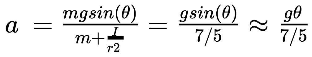 for small angles. This means that the force on the ball is proportional to the angle of the plate. If we ignore higher-order rotation effects and assume that the x and y axes move independently of one another, the motion in the x direction and y direction can be assumed to be uncoupled from one another. This means that we could tune each axis independently. We review the validity of this assumption later, but this proved a strong starting point.
PID is a simple control scheme that uses the current error, defined as the difference between the desired position minus the current position, in order to generate a control signal to reduce this error to zero. The scheme has 3 specific components with different coefficients which are summed to generate the final control signal.
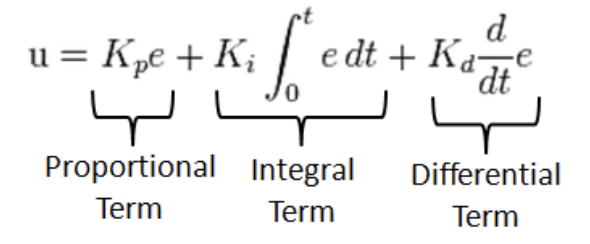
Where “e” is the error between the desired and actual position of the ball in a single direction. The proportional term, Kp, reduces the error based on the size of the error.
The derivative term, Kd, decreases the speed that the error is changing to reduce oscillation.
The integral term, Ki, decreases steady state error in the system to decrease the error to zero when the proportional and derivative terms aren't changing.
There were a number of different types of control schemes that would work for this project. We decided to use a PID due to its natural simplicity and our past experience with it. We made another software tradeoff by reading from the touch screen directly instead of using the STMPE610 resistive touch screen driver to read positions over SPI. We did this because we had a stronger understanding of the workings of the touch screen than of SPI and wanted to keep our system as simple as possible. However, we did use that board as a pinout for the touch screen connections.
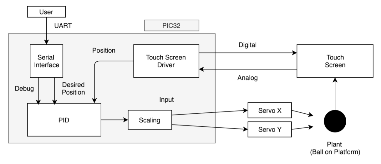
Figure 3 displays the general structure of our system. The resistive touch screen outputted an analog signal for x and y positions of a single touch when driven with a digital input. We used this to identify the current position of the ball on the platform. The value was used by a tuned PID controller in both the x and y directions to output PWM signals to the x and y servos. In order to control the angle of the plate, we fixed the plate in the middle to a 2 DOF axis capable of allowing pivoting but not rotating. The sides of the plate were connected to servo arms used to control the exact angles. This changed the acceleration, velocity, and position of the ball according to the math above, creating a closed control loop.
We decided to build as simple and consistent a hardware setup as possible in order to create reproducible results between days of testing. To increase consistency, we also created a solderboard with pinouts for each servo, the touchscreen, and a ribbon cable to the PIC32. Were a servo to break, or the screen to fail, those components could be easily replaced.
We used a 4 pin resistive touch screen, 2 MG995 analog servos, and the PIC32 with the big board. [4] This used PWM communication with the servos and UART serial communication between the microcontroller and computer. This project was done for educational purposes with no commercialization. There were no relevant copyrights.
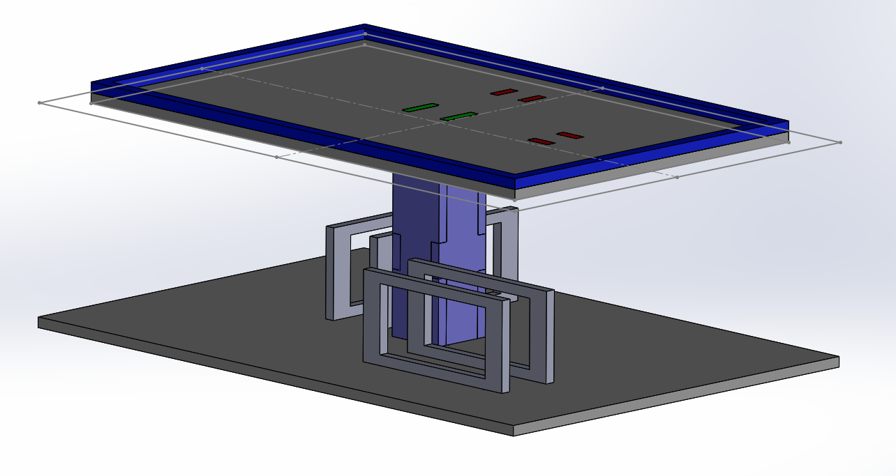
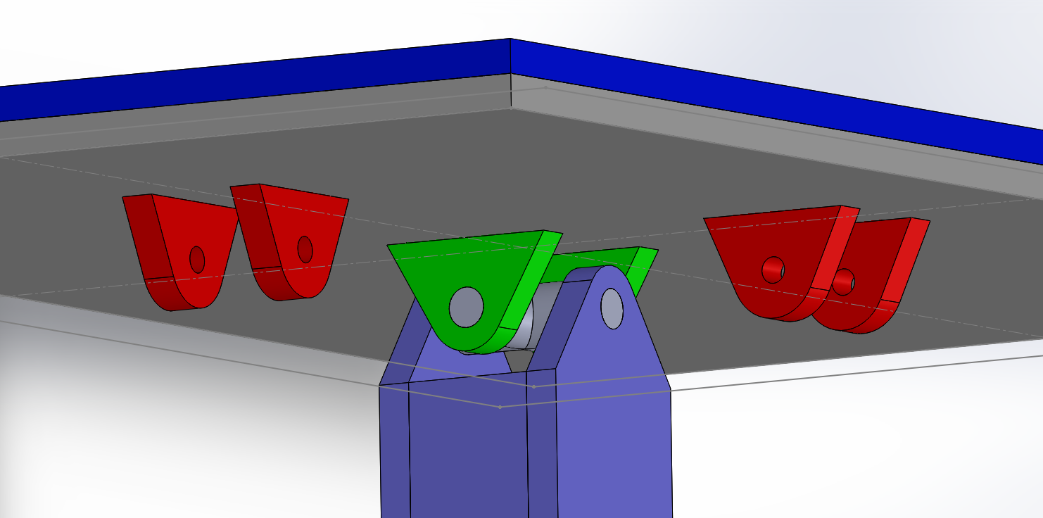
The body of the system was built with rapid prototyping materials: acrylic and 3D printed PETG. We used a wide base in order to prevent slipping and tipping as the servos actuated quickly. A rectangular column connected in the center to lift the platform off of the base. In order to connect the platform to the column in a way that prevented rotation about the column’s vertical axis but allowing pivoting in the other two directions, we used a cross axis connected to pivots on either end. This piece had curved geometry in multiple dimensions and had to be printed instead of laser cut from acrylic. The servos were mounted horizontally along the base through acrylic collars that connected them firmly. Servo rods extended from the servo arm to a ball socket connected to the platform, allowing control in one dimension, and a free pivot in the other. The resistive touch screen itself sat on top of the platform, connected with double-sided tape.
The exact relationship between the throw of the servo arm and the angle change of the platform was very important to the behavior of the system. However, as long as the servos allowed a reasonable angle change, all further mapping could be achieved in software. Our final angle range was +/-16° from horizontal in y and +/-18° in x. This was restricted by the pivot mechanism.
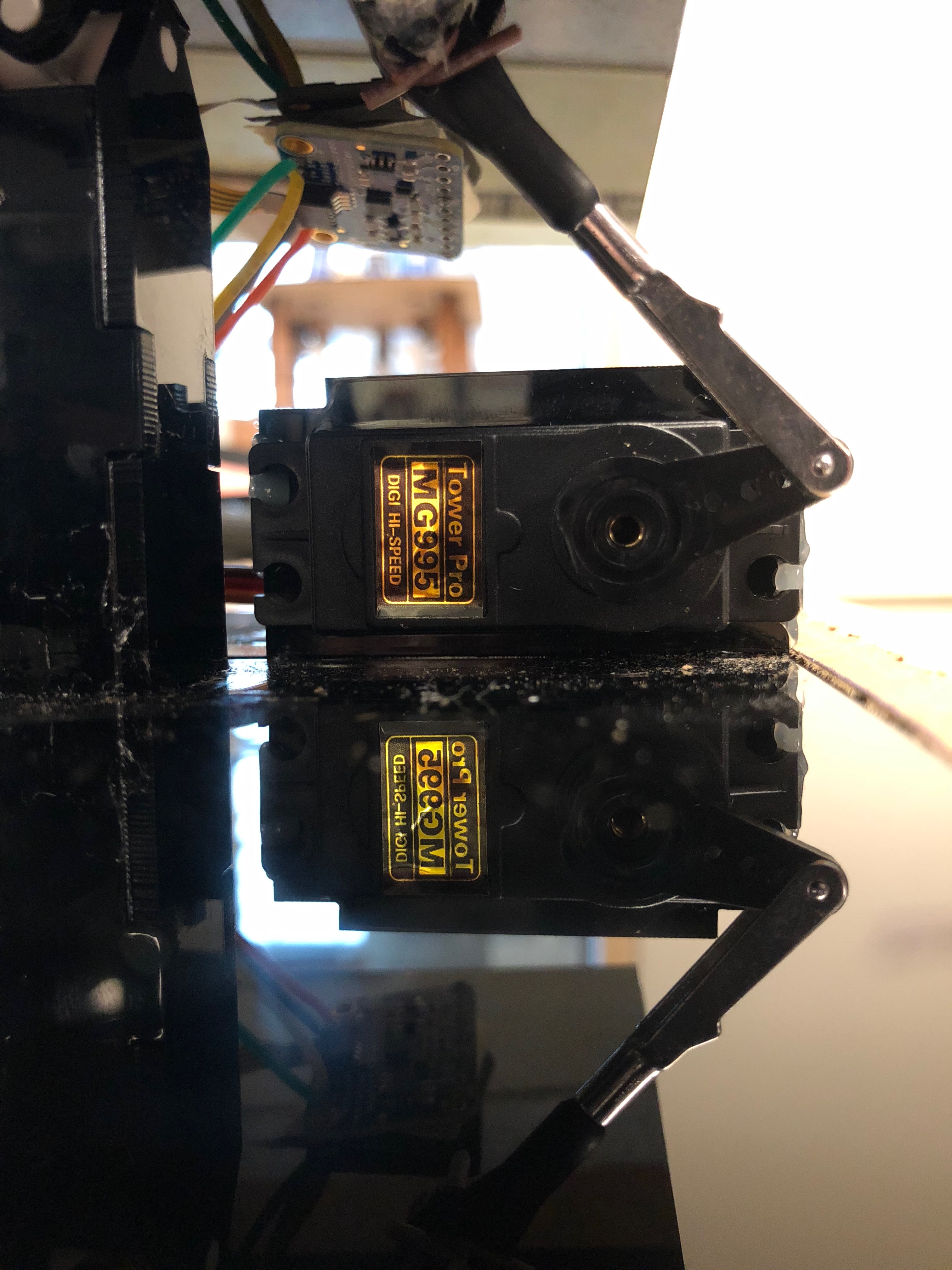
We got our servos from the ECE 4760 lab. Initial calculations found that we required servos with 3.75 kg*cm which was far less than the stall torque of 9.4 kg*cm of these servos at 4.4V.
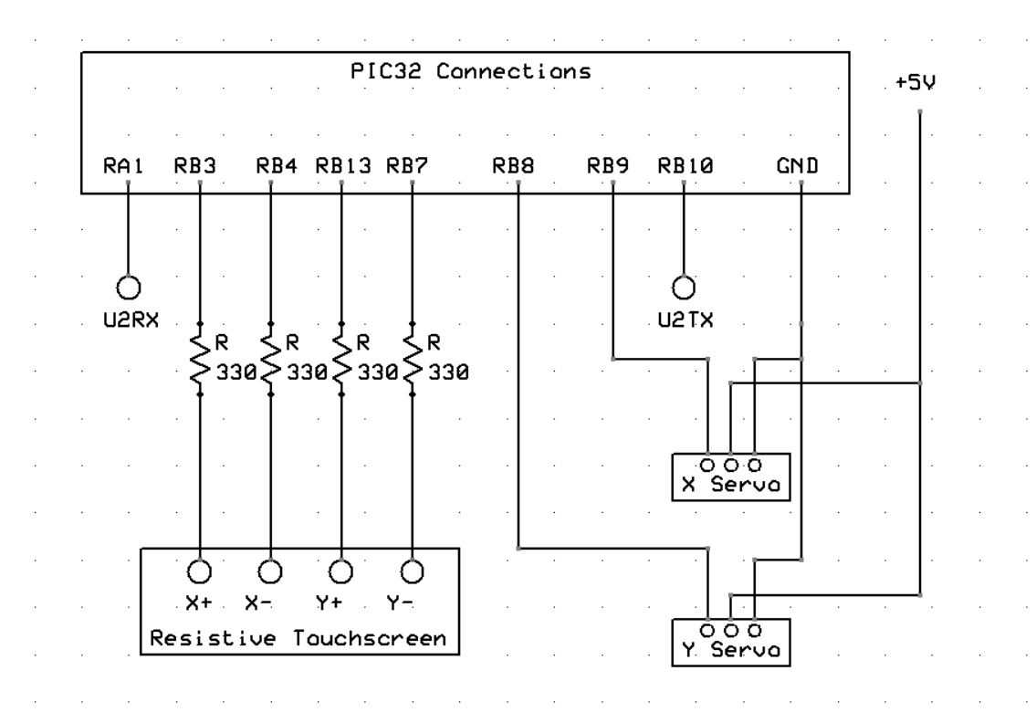
The 330-Ohm resistors were used as an added protection for input pins. Since we wanted to keep our options open for using those pins while driving the touchscreen, a resistor was placed on all four connections. Due to the consistency of the touchscreen, hardware filtering was not necessary. A separate 5V supply drove the servo motors, while the touchscreen and PWM signals were driven using the PIC32’s internal 3.3V logic high. The UART connections were permanently set as inputs and outputs, and therefore required no extra electrical components.
In general our software resembles source code from lab 3 of ECE 4760 due to the similar PID control algorithm. We have two scheduled threads and one interrupt service routine, along with several helper functions. Once the ADC channels, timers, and output compare units are set up in main(), The PIC runs through the threads for reading serial data coming from a UART connection (“command” thread), and another for printing information to the TFT screen (“timer” thread). The interrupt service routine takes care of reading input, and setting the pulse-width modulated (PWM) output to the servos. This runs at 2KHz, with a toggle for reading the x and y directions separately at 1KHz each.
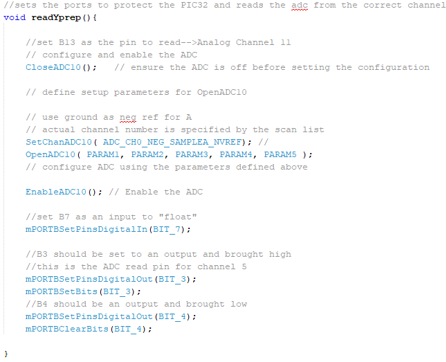
We opted to communicate with the touchscreen directly. The touchscreen works by driving a voltage across two pins of the screen, either +x and -x, or +y and -y. A third pin, +x if we were driving across y or vice versa, is used as an ADC read to get position in the other dimension. The last pin is floating in order to not disrupt the reading. We achieved the “float” by setting that pin as a plain input. A more thorough description can be found here.
To set up the ADC, we used channels 11 and 5, on pins B13 and B3, respectively. The sampling mode was set to automatic and this allowed us to change the pins we were reading from on the fly.[12]
Because reading from the x and y directions required two different pin setups, we needed to toggle between reading the ADC pin in each direction. In order to maintain a 1KHz sample rate, we set the frequency of our reading interrupt to 2KHz, and toggled these reads. Assuming that each direction of motion is largely uncoupled, this shouldn’t have much of an effect on the overall control algorithm. It was also important to note that the port needed some time to settle after being set as an ADC input from a digital output. Though we do not know the exact required time for this settling, by prepping the next directions read after reading the other, we gave the ADC 1/2kHz = 0.5ms to settle which worked consistently.
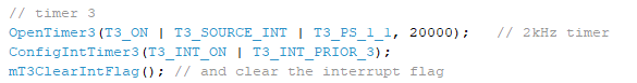
We used timer3 to control the interrupt for screen reading and servo control, and set the frequency to 2kHz:
For our control scheme we considered state-space, lead-lag, and PID setups but decided to go with PID due to our familiarity with the control scheme and our lack of knowledge about the system constants. Our scheme was separated into PID controllers for the x and y directions separately. This was due to the different geometry of the system in the y direction and x direction. However, each system operated the same other than small changes in tuning parameters.
Tuning this system required a significant amount of trial and error. While not fully optimized, what follows are details on a system that worked and why. For every two evaluations of the control thread (once every millisecond), the position was measured and converted to the distance, in tenths of mm, from one corner of the screen. We then took the difference between the current position and desired and defined it as the current error. This value, which was on the order of 100s, was negative if the position was higher than desired and positive if it was lower. Before being used by the control scheme, this value was passed through a digital low pass filter in order to smooth the input signal.

The low pass filter constant was also made tunable through the command line. Our proportional term had final units of pwm signal, order of 1000s. Therefore our initial P term had to be on the order of 1s to 10s for an appropriate response. The derivative gain was found using an averaging method. An array of the five most recent error terms was saved and the derivative of error was defined as the difference between the first and last terms. By using a larger range, we reduced the percent of the term that was dominated by noise. However, we did not want to take too many samples or else our final derivative term would lag the system by too much. Empirical testing found that 5 samples was appropriate. This value was on the order of 10s, so initial values on the order of 100s was appropriate. We were unable to stabilize the system enough for the low frequency error to make a significant difference so we had no integral gain, though we added code with an anti-windup integrator.
In order to actually tune the system we had to first consider its dynamics. The most important term of PID for our system was the derivative. A ball on a flat plate without slip only feels drag from the air, a minimal force at low speeds. This meant that our derivative term had to be very high in order to prevent the ball from easily rolling off of the surface or become unstable after minor disturbances. This large term caused the controller to fight any motion from the ball with significant responses. So if the ball was rolling off of one side, even without a proportional term, the motion was slowed considerably. As the result, our proportional term was relatively small and served to only nudge the ball towards the center. Since the platform we were using was relatively small, especially in the x direction, it was very easy for the ball to be thrown off from a relatively small motion. As a result, we decided to keep all constants as small as possible to achieve the best results.
The mechanical design of our system gave the servos a relatively small range of motion. These servos were also designed for torque and not high resolution so our controllable angle resolution was ~3.1° in x and ~2.7° in y. This meant that even small changes in angle had significant effects on the ball's motion so reducing jitter and large movements was especially important. We achieved this by using a low pass filter constant of 0.99. This added significant phase lag but created easy and smooth motions to control.
After a significant amount of time spent tuning, we were able to find a combination of P, D, and alpha (the filter constant) values in both the x and y directions that maintained stability for a significant portion of time without any other changes. However, we tried a number of other strategies while tuning. We suspected that most of our problems came from coupling between the x and y axes and non-linear motion in the servo output. The dynamics of a ball in 2 dimensions does have a coupled term due to higher order effects from the ball’s rotation. However, these effects are minimal in our case and so to an appropriate approximation, the physics of the system are uncoupled. However, the axis mechanism that holds the platform has a small amount of slop in it so motion in one axis can rotate the platform so that large movements in one axis can throw off an otherwise stable other axis. In order to combat this we tried adding coupling terms to the PID system in which the proportional gain in one direction was weighted by the gain in the other, but creating an accurate model of this was a too high-effort and low-reward process.
Another problem came from the fact that servos create rotational motion that was being converted to a linear arm that went back to rotation. If almost parallel, the angle between the servo arm and platform can be approximated as behaving linearly. However, due the geometry of our setup, the servos were acting in a significantly non-linear range, meaning that 5 ticks at one angle was significantly different than 5 ticks on another. To account for this, we gave the proportional term a squared multiplier so that it was no longer linearly proportional. This was equivalent to exponential control. After some tuning, there was no significant results so we returned to the original method for which we had more data and experience. However, we did notice that the driven angle of the platform was significantly smaller in the positive y direction than the negative. By multiplying the Py gain by 1.1 for positions less than 0 in y, we saw better results.
Our final PID values are shown below.| Parameter | Value |
|---|---|
| Px | 0.6 |
| Py | 0.65 |
| Dx | 80 |
| Dy | 80 |
| Alpha x | 0.99 |
| Alpha y | 0.99 |
After the system derived the new pwm value through the control scheme, this value was added to a constant offset that corresponded to the servos at neutral position. This was done because the servos could not take a negative PWM value. Next, this value was passed through a logic gate to restrict the value to the servo range in which the platform was mechanically restricted. These servos were mounted with acrylic and acrylic cement but were strong enough to pull themselves loose and break the setup if allowed, so their motion had to be restricted before the PWM signal was sent to the servos.
During our tuning process we began by tuning each direction independently using a guard rail to restrict the ball's motion. This process allowed us to find very good values for two seperate one degree of freedom controllers but only translated to good starting points for the full two degree of freedom system due to the coupling issues discussed above.
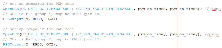
To control the two servo motors, we used two output compare units (OCU) capable of sending PWM signals to each motor. Setting up the OCU’s was fairly simple, and we chose to use pins RB9 and RB8 as our output to the x and y servo respectively.
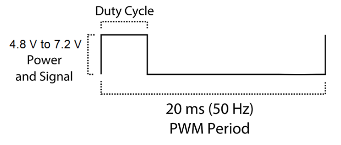
The OCU’s are capable of writing values between 0 and 49,999 corresponding to 0 and 100% duty cycle on the output. Based on the servo motor specifications, we set the OCU’s to output a 20ms period pulse using timer2 with a minimum of about 5% and a maximum of 12.5% duty cycle. Above or below this range (between about 1 and 2.5ms of “on time”) the servos cannot control their angle accurately.
For each servo, we determined the range of valid signals empirically through our UART connection, and then hard coded those bounds in our program. We noticed that the servos only reacted to changes in the pwm cycle of about 200, or about .5% of the full 20ms period. Given this limitation, we noticed that the servos “tick” at some minimum resolution. This caused jitter issues discussed below in the Results section.
Once the servos were attached to the main platform, their range of motion was further limited by our attachment points, and limited placement options for the servos. We empirically calibrated again once they were attached in order to make sure that they didn’t destroy the acrylic mount. So before sending a signal to the servos, the PID output was clamped into this allowed range.
This video describes the device at a high level and includes a demonstration. The ball was not balanced over long periods of time, primarily because the range of its movement was large compared to the size of the screen, especially in the y direction. This meant that most of the failures we saw were due to small movements in the servos kicking the ball off of the screen when the ball was already very close to the edge. When this did not happen, the platform was capable of consistently decreasing the amplitude of oscillations while keeping the ball on the screen.
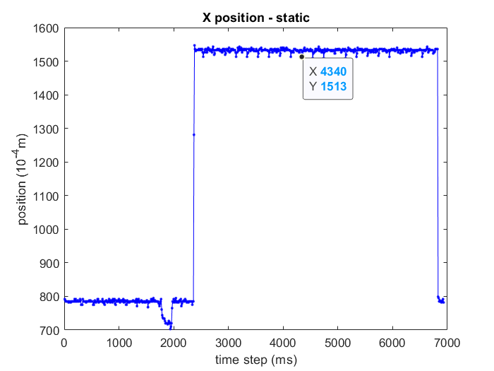
As you can see in the video above, there was some jitter due to the large angle between “ticks” of the servo, so the minimum resolution of the servo control was quite large. Below is a plot of the microcontroller’s reading of position of a finger pressed on a specific position at about 2.5s. The variation is small but still present with an amplitude of 0.28 mm and a frequency of 5Hz. The amplitude was well below the range of stabilization so it was accurate enough for our uses. We're unsure where this regular spike behavior came from but it did not make a difference to our final design. We used this data in order to size the filter as well as set expectations on precision of control.
The next plot is of the x and y position of the ball while freely moving. The ball stayed within a rectangle defined by the edges in y and +/-5cm in x. It is clear that the x position is relatively regular noise centered about 4cm while the y position leans heavily toward one direction, a result of the non-linear servo motion, and a source of consistent problems.
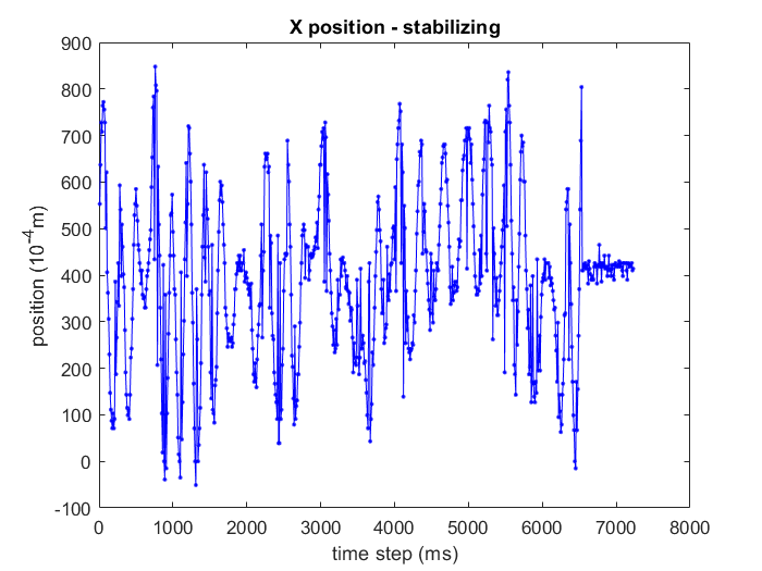
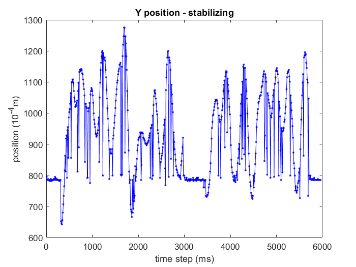
Our final controller was capable of keeping the ball on the platform for significant portions of time. However, there was large variation in position during this stabilization so numbers such as rise time and settling time are not meaningful to quantify. Over 10 trials our average stabilization time was 15-20s seconds with some trials greater than 1 minute. The vast majority of the time the ball fell off in the y direction. This suggested to us that if the platform was equal length in y as x, the stabilization would be greatly improved.
We also provided a rejection mode which flipped the PID tuned PWM value and removed the ball from the table as fast as possible with a command from the UART console. This was very effective though relatively useless.
This project doesn’t have much interaction with a user, other than placing the ball on the surface.
We were overall very satisfied with the result of our project. Due to the short period of time and limited resources, our minimum expectation for the project was stabilization in one dimension. We were very pleased to have achieved basic stabilization in two dimensions as well. Another goal of ours was to create a simple and elegant hardware setup that could be easily replicated. The footprint of our design was only slightly larger than the platform and we reduced the amount of loose wiring with a solder board. We also made the servos easily replaceable. We considered this a success.
The majority of our problems came from slop in our platform, low resolution of servo motors, and a short stabilization distance in the y direction. In the future we would create a slightly taller pedestal with a tighter fit axis that allows the servos a larger range of motion. In addition, we would likely see better results with a larger platform. With these changes, we also might be able to try different types of controllers and observers. Optimal control using a linear quadratic regulator in particular would be very interesting to try on this simple system. [3]
A significant portion of our code structure came from the code written for Lab 3 of ECE 4760. As the result, two members of that group, Salah Hassen and Samad Arshad, are attributed for parts of their code. The resources and code structure made available by Bruce Land and the course staff were also used.
We also referenced this video for inspiration on the project. We hope to achieve similar results from future efforts.
This project was consistent with all IEEE standards. The only potentially dangerous element was the moving metal ball. During the testing phase we built a box to protect the user and proceeded with caution when this box was removed for demonstration. There was no human connected component of this project so electrical dangers were minimal.
The group approves this report for inclusion on the course website.
The group approves the video for inclusion on the course youtube channel.
| Item Name | Vendor | # Of Parts | Price ($) | Total ($) |
|---|---|---|---|---|
| Big Board | Lab | 1 | 10 | 10 |
| MicroStickII | Lab | 1 | 1 | 1 |
| Jumper cables | Lab | 8 | 0.10 | 0.80 |
| Solder Board | Greg | 1 | 0 | 0 |
| Power Supply | Lab | 2 | 5 | 10 |
| PIC32MX250F128B | Lab | 1 | 5 | 5 |
| TFT LCD | Lab | 1 | 10 | 10 |
| Header Socket | Lab | 39 | 0.05 | 1.95 |
| Acrylic | Lab | 16 | 0 | 0 |
| Servos | Lab | 2 | 0 | 0 |
| Quik Link Clevis | Amazon | 1 | 2.09 | 2.09 |
| 4-40 Threaded Rod | Amazon | 1 | 7.43 | 7.43 | Swivel Ball Link for 4-40, 2-56 | Amazon | 1 | 6.50 | 6.50 | Steel Ball | McMaster | 1 | 5.74 | 5.74 |
| 3D Printed Part | Greg | 1 | 0 | 0 |
| I/O Expander | Lab | 1 | 5 | 5 | Resistive Touch Screen | Adafruit | 1 | 14.95 | 14.95 | STMPE610 Touch Screen Breakout | Adafruit | 1 | 9.95 | 9.95 | Total Cost | 90.41 |
| Task | Member |
|---|---|
| Mechanical Design | Sam |
| Electrical Design | Greg |
| Position Read Software | Greg |
| PID Control Scheme | Sam |
| Tuning | Both |
[1] Similar Project
[2] Servo Motor Datasheet
[3] Andrews, Greg, Chris Colasuonno, and Aaron Herrmann. ”Ball on Plate Balancing System”
ECSE-4962 Control Systems Design Final Project Report April 28, 2004, Rensselaer Polytechnic Institute.
[4] ECE 4760 Development Boards
[5] ECE 4760 UART serial
[6] ECE 4760 Time Measurement and Control
[7] ECE 4760
[8] Touchscreen Source
[9] Touchscreen Physics Reference
[10] STMPE610 Touchscreen Driver
[11] 3DOF Stewart Platform
[12]ECE 4760 I/O Ports
[13]Autonomously Hovering Quadcopter
/*
 * File:        AEP's Can Do Anything Source Code
 * 2 DOF PID Controller for Ball Balancing Platform
 * Author:      Samuel Feibel and Gregory Kaiser (sof23 & ghk48)
 * Adapted from code written by Bruce Land for ECE 4760
 *
 * For use with Sean Carroll's Big Board
 * Written for ECE 4760 Final Project
 * Fall 2019
 * Target PIC:  PIC32MX250F128B
 */

////////////////////////////////////
// clock AND protoThreads configure!
// You MUST check this file!
#include "config_1_3_2.h"
// threading library
#include "pt_cornell_1_3_2.h"

////////////////////////////////////
// graphics libraries
#include "tft_master.h"
#include "tft_gfx.h"
// need for rand function
#include

// include for fixed point
#include
#include

////////////////////////////////////

//macros for transforming types
#define float2Accum(a) ((_Accum)(a))
#define Accum2float(a) ((float)(a))
#define int2Accum(a) ((_Accum)(a))
#define Accum2int(a) ((int)(a))

// Mapping Constants
#define min_x 280.0
#define min_y 380.0
#define max_x 730.0
#define max_y 611.0
#define dist_x 1530.0
#define dist_y 920.0
#define convert_x dist_x/(max_x-min_x)
#define convert_y dist_y/(max_y-min_y)


// Param Define for ADC
// define setup parameters for OpenADC10
	// Turn module on | ouput in integer | trigger mode auto | enable autosample
    // ADC_CLK_AUTO -- Internal counter ends sampling and starts conversion (Auto convert)
    // ADC_AUTO_SAMPLING_ON -- Sampling begins immediately after last conversion completes; SAMP bit is automatically set
    // ADC_AUTO_SAMPLING_OFF -- Sampling begins with AcquireADC10();
    #define PARAM1  ADC_FORMAT_INTG16 | ADC_CLK_AUTO | ADC_AUTO_SAMPLING_ON //

	// define setup parameters for OpenADC10
	// ADC ref external  | disable offset test | disable scan mode | do 1 sample | use single buf | alternate mode off
	#define PARAM2  ADC_VREF_AVDD_AVSS | ADC_OFFSET_CAL_DISABLE | ADC_SCAN_ON | ADC_SAMPLES_PER_INT_2 | ADC_ALT_BUF_OFF | ADC_ALT_INPUT_OFF

	// Define setup parameters for OpenADC10
    // use peripherial bus clock | set sample time | set ADC clock divider
    // ADC_CONV_CLK_Tcy2 means divide CLK_PB by 2 (max speed)
    // ADC_SAMPLE_TIME_5 seems to work with a source resistance < 1kohm
    #define PARAM3 ADC_CONV_CLK_PB | ADC_SAMPLE_TIME_15 | ADC_CONV_CLK_Tcy

	// define setup parameters for OpenADC10
	// set AN11 and AN5  as analog inputs
	#define PARAM4	ENABLE_AN11_ANA | ENABLE_AN5_ANA //

	// define setup parameters for OpenADC10
    // DO not skip the channels you want to scan
    // do not specify channels  5 and 11
	#define PARAM5	SKIP_SCAN_AN0 | SKIP_SCAN_AN1 | SKIP_SCAN_AN2 | SKIP_SCAN_AN3 | SKIP_SCAN_AN4 | SKIP_SCAN_AN6 | SKIP_SCAN_AN7
| SKIP_SCAN_AN8 | SKIP_SCAN_AN9 | SKIP_SCAN_AN10 | SKIP_SCAN_AN12 | SKIP_SCAN_AN13 | SKIP_SCAN_AN14 | SKIP_SCAN_AN15
// end ADC Param Define

// PWM Variables
volatile int generate_period = 50000; //The actual period of the wave - 50Hz
volatile int pwm_on_timex = 4800 ;  //time pwm output is on in respect to generate period servo x
volatile int pwm_on_timey = 1500 ;  //time pwm output is on in respect to generate period servo y

// Limitations for Servo Position
#define pwm_x_min 3500
#define pwm_x_max 5500
#define pwm_y_min 2000
#define pwm_y_max 3500

// string buffer
char buffer[60];

// === thread structures ============================================

//print lock
static struct pt_sem print_sem ;

// thread control structs
// note that UART input and output are threads
static struct pt pt_timer, pt_cmd;
// The following threads are necessary for UART control
static struct pt pt_input, pt_output, pt_DMA_output ;

// system 1 second interval tick
int sys_time_seconds ;


// === print utilities ==============================================
// print a line on the TFT
// string buffer
char buffer[60];
void printLine(int line_number, char* print_buffer, short text_color, short back_color){
    // line number 0 to 31
    /// !!! assumes tft_setRotation(0);
    // print_buffer is the string to print
    int v_pos;
    v_pos = line_number * 10 ;
    // erase the pixels
    tft_fillRoundRect(0, v_pos, 239, 8, 1, back_color);// x,y,w,h,radius,color
    tft_setTextColor(text_color);
    tft_setCursor(0, v_pos);
    tft_setTextSize(1);
    tft_writeString(print_buffer);
}

void printLine2(int line_number, char* print_buffer, short text_color, short back_color){
    // line number 0 to 31
    /// !!! assumes tft_setRotation(0);
    // print_buffer is the string to print
    int v_pos;
    v_pos = line_number * 20 ;
    // erase the pixels
    tft_fillRoundRect(0, v_pos, 239, 16, 1, back_color);// x,y,w,h,radius,color
    tft_setTextColor(text_color);
    tft_setCursor(0, v_pos);
    tft_setTextSize(2);
    tft_writeString(print_buffer);
}


//sets the ports to protect the PIC32 and reads the adc from the correct channel
void readYprep(){

    //set B13 as the pin to read-->Analog Channel 11
    // configure and enable the ADC
	CloseADC10();	// ensure the ADC is off before setting the configuration

	// define setup parameters for OpenADC10

	// use ground as neg ref for A
    // actual channel number is specified by the scan list
    SetChanADC10( ADC_CH0_NEG_SAMPLEA_NVREF); //
	OpenADC10( PARAM1, PARAM2, PARAM3, PARAM4, PARAM5 ); // configure ADC using the parameters defined above

	EnableADC10(); // Enable the ADC

    //set B7 as an input to "float"
    mPORTBSetPinsDigitalIn(BIT_7);

    //B3 should be set to an output and brought high
    //this is the ADC read pin for channel 5
    mPORTBSetPinsDigitalOut(BIT_3);
    mPORTBSetBits(BIT_3);
    //B4 should be an output and brought low
    mPORTBSetPinsDigitalOut(BIT_4);
    mPORTBClearBits(BIT_4);

}

void readXprep(){
    //set B3 as the pin to read-->Analog Channel 5

    // configure and enable the ADC
	CloseADC10();	// ensure the ADC is off before setting the configuration

	// define setup parameters for OpenADC10

	// use ground as neg ref for A
    // actual channel number is specified by the scan list
    SetChanADC10( ADC_CH0_NEG_SAMPLEA_NVREF); //
	OpenADC10( PARAM1, PARAM2, PARAM3, PARAM4, PARAM5 ); // configure ADC using the parameters defined above

	EnableADC10(); // Enable the ADC

    //B4 set to "floating" for reading
    mPORTBSetPinsDigitalIn(BIT_4);
    //B13 should be set to an output and brought high
    //this was the ADC read pin for reading channel 11
    mPORTBSetPinsDigitalOut(BIT_13);
    mPORTBSetBits(BIT_13);

    //B7 should be an output and brought low
    mPORTBSetPinsDigitalOut(BIT_7);
    mPORTBClearBits(BIT_7);

}

static int adc_11, adc_5, junk;
// PID Variables
volatile _Accum Px = .6; // Proportional Control Constant
volatile _Accum Ix = 0.0;  // Integral Control Constant
volatile int Dx = 80; // Derivative Control Constant
volatile _Accum Py = .65; // Proportional Control Constant
volatile _Accum Iy = 0.0;  // Integral Control Constant
volatile int Dy = 80; // Derivative Control Constant
static int toggle = 0; // 1 ->x, 0 ->y
static int pos_x, pos_y; //position
static int error_x, error_y;
static int desired_x=900, desired_y=400;
static int debug;
static int prev_error_x = 0, prev_error_y =0;
static int d_error_x, d_error_y;
static int arr_error_x[5];// = {0,0,0,0,0};
static int arr_error_y[5];
static int error_integ_x=0, error_integ_y=0;
double alpha_x = 0.99;  //Low Pass Filter constant
double alpha_y = 0.99;  //Low Pass Filter constant
int i;
int arr_error_l = 4;
int dump  = 0;  // 0 for stabilization mode, 1 for rejection mode

// == Timer 3 ISR =====================================================
void __ISR(_TIMER_3_VECTOR, ipl3) Timer3Handler(void){
    // clear the timer interrupt flag
    mT3ClearIntFlag();

    if(toggle == 1){    // X stuff
        // Read and scale position
        adc_5 = ReadADC10(0);
        pos_x = (adc_5-min_x)*convert_x;
        //PIDX

        // find error through low pass filter
        error_x = (int) (error_x*alpha_x+ (1-alpha_x)*(desired_x-pos_x));//desired_x - pos_x;

        // P term
        pwm_on_timex = Px*error_x;

        // D term
        // take averaged step between errors
        for(i=1;i pwm_x_max){
            pwm_on_timex = pwm_x_max;
        }
        if(pwm_on_timex < pwm_x_min){
            pwm_on_timex = pwm_x_min;
        }

        // Output variable
        SetDCOC3PWM(pwm_on_timex);

        // Prepare y for next read
        readYprep();
        toggle = 0;
    }
    else{   // Y stuff
        // read and scale position
        adc_11 = ReadADC10(1);
        pos_y = (adc_11-min_y)*convert_y;

        // find error with low pass filter
        error_y = (int) (error_y*alpha_y + (1-alpha_y)*(desired_y-pos_y));//desired_x - pos_x;

        // P term
        if(error_y>0){
            pwm_on_timey = 1.1*Py*error_y;
        }
        else{
            pwm_on_timey = Py*error_y;
        }

        // D term
        // take averaged step between errors
        for(i=1;i0){
            pwm_on_timey = pwm_on_timey + 1.1*Dy*d_error_y;
        }else{
            pwm_on_timey = pwm_on_timey + Dy*d_error_y;
        }


        //Integral term
        if( Iy == 0){
            error_integ_y = 0;
        }else{
            error_integ_y = error_integ_y + error_y;
        }

        pwm_on_timey = pwm_on_timey + Iy*error_integ_y;

        // Flip PWM signal for rejection
        if (dump == 1){
            pwm_on_timey = -pwm_on_timey;
        }

        // Scale to center of platform
        pwm_on_timey= -pwm_on_timey + 2800;

        //debug for retuning
//        pwm_on_timey = Py;

        // Bound values to mechanical limits
        if(pwm_on_timey > pwm_y_max){
            pwm_on_timey = pwm_y_max;
        }
        if(pwm_on_timey < pwm_y_min){
            pwm_on_timey = pwm_y_min;
        }

        // Output variable
        SetDCOC2PWM(pwm_on_timey);

        // Prepare x for next read
        readXprep();
        toggle = 1;
    }
}

// === Command Thread ======================================================
// The serial interface
static char cmd[16];
static int value_i;
static float value_f;
static _Accum value_a;
int desired_value;
int desired_angle;

static PT_THREAD (protothread_cmd(struct pt *pt))
{
    PT_BEGIN(pt);
      while(1) {

            // send the prompt via DMA to serial
            sprintf(PT_send_buffer,"cmd>");
            // by spawning a print thread
            PT_SPAWN(pt, &pt_DMA_output, PT_DMA_PutSerialBuffer(&pt_DMA_output) );

          //spawn a thread to handle terminal input
            // the input thread waits for input
            // -- BUT does NOT block other threads
            // string is returned in "PT_term_buffer"
            PT_SPAWN(pt, &pt_input, PT_GetSerialBuffer(&pt_input) );
            // returns when the thread dies
            // in this case, when  is pushed
            // now parse the string
             sscanf(PT_term_buffer, "%s %d", cmd, &value_i);
             sscanf(PT_term_buffer, "%s %f", cmd, &value_f);
             value_a = float2Accum(value_f);

             if (cmd[0]=='p'&&cmd[1]=='x') { //x servo, p term
                 Px = value_a;
                 sprintf(PT_send_buffer,"Px=%f\n", Accum2float(Px));
                 PT_SPAWN(pt, &pt_DMA_output, PT_DMA_PutSerialBuffer(&pt_DMA_output) );
                 //sprintf(buffer, "Px = %d", Px);
                 //printLine(12, buffer, ILI9340_WHITE, ILI9340_BLACK);
             }
             if (cmd[0]=='p'&&cmd[1]=='y') { //y servo, p term
                 Py = value_a;
                 sprintf(PT_send_buffer,"Py=%f\n", Accum2float(Py));
                 PT_SPAWN(pt, &pt_DMA_output, PT_DMA_PutSerialBuffer(&pt_DMA_output) );
                 //sprintf(buffer, "Py = %d", Py);
                 //printLine(12, buffer, ILI9340_WHITE, ILI9340_BLACK);
             }
             if (cmd[0]=='d'&&cmd[1]=='x') { //x servo, d term
                 Dx = value_i;
                 sprintf(PT_send_buffer,"Dx=%d\n", Dx);
                 PT_SPAWN(pt, &pt_DMA_output, PT_DMA_PutSerialBuffer(&pt_DMA_output) );
                 //sprintf(buffer, "Dx = %d", Dx);
                 //printLine(12, buffer, ILI9340_WHITE, ILI9340_BLACK);
             }
             if (cmd[0]=='d'&&cmd[1]=='y' ) { //y servo, d term
                 Dy = value_i;
                 sprintf(PT_send_buffer,"Dy=%f\n", Dy);
                 PT_SPAWN(pt, &pt_DMA_output, PT_DMA_PutSerialBuffer(&pt_DMA_output) );
                 //sprintf(buffer, "Dy = %d", Dy);
                 //printLine(12, buffer, ILI9340_WHITE, ILI9340_BLACK);
             }
             if (cmd[0]=='i'&&cmd[1]=='x' ) { //x servo, i term
                 Ix = value_a;
                 sprintf(PT_send_buffer,"Ix=%f\n", Accum2float(Ix));
                 PT_SPAWN(pt, &pt_DMA_output, PT_DMA_PutSerialBuffer(&pt_DMA_output) );
                 //sprintf(buffer, "Ix = %d", Ix);
                 //printLine(12, buffer, ILI9340_WHITE, ILI9340_BLACK);
             }
             if (cmd[0]=='i'&&cmd[1]=='y' ) { //y servo, i term
                 Iy = value_a;
                 sprintf(PT_send_buffer,"Iy=%f\n", Accum2float(Iy));
                 PT_SPAWN(pt, &pt_DMA_output, PT_DMA_PutSerialBuffer(&pt_DMA_output) );
                 //sprintf(buffer, "Iy = %d", Iy);
                 //printLine(12, buffer, ILI9340_WHITE, ILI9340_BLACK);
             }
             if (cmd[0]=='a'&&cmd[1]=='x' ) { //x servo, desired position
                 desired_x = value_i;
                 sprintf(PT_send_buffer,"posx=%d\n", desired_x);
                 PT_SPAWN(pt, &pt_DMA_output, PT_DMA_PutSerialBuffer(&pt_DMA_output) );
                 //sprintf(buffer, "desx = %d", desired_x);
                 //printLine(12, buffer, ILI9340_WHITE, ILI9340_BLACK);
             }
             if (cmd[0]=='a'&&cmd[1]=='y' ) { //y servo, desired position
                 desired_y = value_i;
                 sprintf(PT_send_buffer,"posy=%d\n", desired_y);
                 PT_SPAWN(pt, &pt_DMA_output, PT_DMA_PutSerialBuffer(&pt_DMA_output) );
                 //sprintf(buffer, "posy = %d", desired_y);
                 //printLine(12, buffer, ILI9340_WHITE, ILI9340_BLACK);
             }
             if (cmd[0]=='f'&&cmd[1]=='x') { //alpha value x
                 alpha_x = value_a;
                 sprintf(PT_send_buffer,"alpha_x=%f\n", Accum2float(alpha_x));
                 PT_SPAWN(pt, &pt_DMA_output, PT_DMA_PutSerialBuffer(&pt_DMA_output) );
                 //sprintf(buffer, "posy = %d", desired_y);
                 //printLine(12, buffer, ILI9340_WHITE, ILI9340_BLACK);
             }
             if (cmd[0]=='f'&&cmd[1]=='y') { //alpha value y
                 alpha_y = value_a;
                 sprintf(PT_send_buffer,"alpha_y=%f\n", Accum2float(alpha_y));
                 PT_SPAWN(pt, &pt_DMA_output, PT_DMA_PutSerialBuffer(&pt_DMA_output) );
                 //sprintf(buffer, "posy = %d", desired_y);
                 //printLine(12, buffer, ILI9340_WHITE, ILI9340_BLACK);
             }
             if (cmd[0]=='l' ) { //all info command
                 //sprintf(PT_send_buffer,"Px=%f Dx=%d Ix=%f posx=%d; Py=%f Dy=%d Iy=%f posy=%d ; alpha=%f\n", Accum2float(Px),Dx
,Accum2float(Ix),desired_x,Accum2float(Py),Dy,Accum2float(Iy),desired_y,Accum2float(alpha));

                 sprintf(PT_send_buffer,"Px=%f Dx=%d fx=%f; Py=%f Dy=%d fy=%f", Accum2float(Px),Dx,alpha_x,Accum2float(Py),Dy,alpha_y);
                 PT_SPAWN(pt, &pt_DMA_output, PT_DMA_PutSerialBuffer(&pt_DMA_output) );
                 //sprintf(buffer, "posy = %d", desired_y);
                 //printLine(12, buffer, ILI9340_WHITE, ILI9340_BLACK);
             }
             if (cmd[0]=='z') { //Rejection/stabilization mode toggle command
                 if (dump == 0){
                     dump = 1;
                 }
                 else{
                     dump = 0;
                 }
                 sprintf(PT_send_buffer,"alpha_y=%f\n", Accum2float(alpha_y));
                 PT_SPAWN(pt, &pt_DMA_output, PT_DMA_PutSerialBuffer(&pt_DMA_output) );
                 //sprintf(buffer, "posy = %d", desired_y);
                 //printLine(12, buffer, ILI9340_WHITE, ILI9340_BLACK);
             }

            // never exit while
      } // END WHILE(1)
  PT_END(pt);
} // thread 2

// === Display Thread =================================================
// Display current info
static PT_THREAD (protothread_timer(struct pt *pt))
{
    PT_BEGIN(pt);
      while(1) {
        // yield time .01 second
        PT_YIELD_TIME_msec(10) ;
        sys_time_seconds++ ;

        // Print mode
        if (dump == 0){
            sprintf(buffer,"Mode: Stabilization");
        }
        else{
            sprintf(buffer,"Mode: Rejection");
        }
        // Print PWM Values
        printLine2(1, buffer, ILI9340_YELLOW, ILI9340_BLACK);
        sprintf(buffer,"pwmx: %d", pwm_on_timex);
        printLine2(2, buffer, ILI9340_YELLOW, ILI9340_BLACK);
        sprintf(buffer,"pwmy: %d", pwm_on_timey);
        printLine2(3, buffer, ILI9340_YELLOW, ILI9340_BLACK);

        // Print Position
        sprintf(PT_send_buffer,"%d ", pos_x);
        PT_SPAWN(pt, &pt_DMA_output, PT_DMA_PutSerialBuffer(&pt_DMA_output) );
        // NEVER exit while
      } // END WHILE(1)
  PT_END(pt);
} // timer thread


// === Main  ======================================================
void main(void) {
 //SYSTEMConfigPerformance(PBCLK);

    ANSELA = 0; ANSELB = 0;

    // === config threads ==========
    // turns OFF UART support and debugger pin, unless defines are set
    PT_setup();

    // === setup system wide interrupts  ========
    INTEnableSystemMultiVectoredInt();

    // the ADC ///////////////////////////////////////
    // configure and enable the ADC
	CloseADC10();	// ensure the ADC is off before setting the configuration

	// use ground as neg ref for A
    // actual channel number is specified by the scan list
    SetChanADC10( ADC_CH0_NEG_SAMPLEA_NVREF); //
	OpenADC10( PARAM1, PARAM2, PARAM3, PARAM4, PARAM5 ); // configure ADC using the parameters defined above

	EnableADC10(); // Enable the ADC///////////////////////////////////////////////////////

    ////set the non-adc pins as outputs
    //set port B4 to output and set it low
    mPORTBSetPinsDigitalOut(BIT_4);
    mPORTBClearBits(BIT_4);
    //set port A3 to be an output and set it low
    mPORTASetPinsDigitalOut(BIT_3);
    mPORTAClearBits(BIT_3);

    // timer 3
    OpenTimer3(T3_ON | T3_SOURCE_INT | T3_PS_1_1, 20000);   // 2kHz timer
    ConfigIntTimer3(T3_INT_ON | T3_INT_PRIOR_3);
    mT3ClearIntFlag(); // and clear the interrupt flag

    // set up timer2 to generate the wave period
    OpenTimer2(T2_ON | T2_SOURCE_INT | T2_PS_1_16, generate_period);

    // set up compare3 for PWM mode
    OpenOC3(OC_ON | OC_TIMER2_SRC | OC_PWM_FAULT_PIN_DISABLE , pwm_on_timex, pwm_on_timex); // pwmx
    // OC3 is PPS group 4, map to RPB9 (pin 18)
    PPSOutput(4, RPB9, OC3);

    // set up compare2 for PWM mode
    OpenOC2(OC_ON | OC_TIMER2_SRC | OC_PWM_FAULT_PIN_DISABLE , pwm_on_timey, pwm_on_timey); //pwmy
    // OC2 is PPS group 2, map to RPB8 (pin 17)
    PPSOutput(2, RPB8, OC2);

    // === setup system wide interrupts  ====================
    INTEnableSystemMultiVectoredInt();

    // init the threads
    PT_INIT(&pt_timer);
    PT_INIT(&pt_cmd);

    // init the display
    tft_init_hw();
    tft_begin();
    tft_fillScreen(ILI9340_BLACK);
    //240x320 vertical display
    tft_setRotation(0); // Use tft_setRotation(1) for 320x240

    // seed random color
    srand(1);

    // set up first cycle read
    readXprep();

    // round-robin scheduler for threads
    while (1){
      PT_SCHEDULE(protothread_timer(&pt_timer));
      PT_SCHEDULE(protothread_cmd(&pt_cmd));
    }
  } // main

// === end  ======================================================