All of the following examples use Protothreads. This means that you need the pt_cornell.h file described below. PIC architecture separates timers, from compare units and from input capture. This means that one timer can drive several output compare units for waveform generation, or act as a time reference for several input compare units. In all the examples, the cpu is running at 64 MHz and the peripherial bus at 32 MHz.
-- This example sets up timer2 to drive two pulse trains from OC2 and OC3. Either of these pulse trains can be hooked to an input capture unit, which uses timer3 as a time reference. Timer three is set up to overflow so that periods are correct when computed from sequential edge capture times. The print thread prints out the generated interval, and the min, max and current value of the captured interval. The command thread listens for user input to set the timer2 period, and a one second clock thread gives system time (using timer5, as explained below in the protothreads section). To run this, download pt_cornell.h and the example code.
-- Example 2 sets up OC3 as a PWM unit with settable timer2 period (and thus PWM resolution) and settable PWM on-time. The on-time is then auto incremented in the timer2 ISR to sweep the on-time from zero to the timer2 period. Setting the timer2 period and OC2 pulse period in the user interface thread is cleaner.
-- Example 3 sets up OC3 as a PWM unit with timer2 period (and thus PWM resolution) equal to 64 cycles (500 kHz). PWM on-time is set by a sine wave Direct Digital Synthesis (DDS) unit. The frequency synthesized is set by the UART user interface. The PWM output (Pin 18) must be passed through an analog lowpass filter. Choose the time constant of the filter consistent with the frequencies you wish to generate. Spectral purity is about 32 db at low frequencies. You could get better spectral purity by increasing the PWM resolution, but that, of course, lowers the sample rate. Eight-bit samples have a PWM sample rate of 125 kHz.
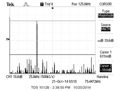
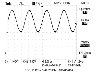
Generating a good sine wave requires a high sample rate, and reasonable accuracy DAC. A DMA channel is used to blast a sine wave (or any other periodic function) out of port B.0 to B.5 and B.7. (Note that B.4 and B.5 have a required config statement to turn off JTAG and clock input and that B.6 does not exist on this package). On a PIC32 running at 60 MHz, the DMA channel can support about 3.5 million bytes/sec in single byte transfer mode triggered by a timer (but with no ISR). The useful frequency range is 10 Hz to 200 KHz. During synthesis, NO cpu cycles are used. The sine table is dynamically sized according to the frequency range to minimize distortion. The sine wave delivered has the highest amplitude error harmonic about 40 db below the fundamental up to 100 KHz and less than 35 db above that frequency. Code is here. Spectrum and waveform of a nominal 80 KHz signal is below.
-- It is useful to get a serial channel running for fairly high speed peripherials. The first device I tried is an Analog Devices AD7303. It is a two channel, 8-bit DAC with buffered voltage output. The channels may be updated simultaneously or separately. Each channel write requires a two-byte transfer to the DAC. The first is a control byte, and the second is the channel data byte. The control byte specifies which channel will be updated as well as the update mode. Each two-byte transfer must be signaled by dropping the voltage on a SYNC pin before the beginning of the transfer, then raising it at the end. Like most microcontrollers the PIC32 SPI interface is simple enough to handle that direct register manipulation is probably the easiest, although the higher level
SpiChnOpen function also worked well. The SPI standard supports four clock phases. The microconctoller master has to match the requirements of the slave. This is often the most annoying part of getting SPI running. Careful analysis of the slave datasheet is required. The AD7303 requires the slave to generate a clock frequency less than 30 MHz, and expects the data to be stable on the the positive clock edge. The required configuration is SpiChnOpen(spiChn, SPI_OPEN_ON | SPI_OPEN_MODE16 | SPI_OPEN_MSTEN | SPI_OPEN_CKE_REV | SPI_OPEN_CKP_HIGH , spiClkDiv);or equivalently:
SPI1CON = 0x8560 ; // SPI on, 16-bit, master, CKE=1, CKP=1

      //The SPI baudrate BR is given by: BR=Fpb/(2*(SPI1BRG+1))

      SPI1BRG = 0;  // Fperipheralbus/2
The basic SPI transaction is to start a simultaneous send/receive. On the DAC used here, no useful data is received, but you must do the receive operation to reset the
SPI1STATbits.SPIRBF flag. For this application the SPI transaction ismPORTBClearBits(BIT_0); // start transaction
SPI1BUF = DAC_cntl_1 | DAC_value ; // write to SPI
while( !SPI1STATbits.SPIRBF); // check for complete transmit
junk = SPI1BUF ; // read the received value (not used by DAC in this example)
mPORTBSetBits(BIT_0); // end transaction You clear the SYNC bit, write to SPI1BUF to trigger the hardware trnasmit/receive, wait for it to finish, then do the manditory read and set the SYNC bit. Connections between the two devices are shown below, assuming a certain PPS setup as shown in the code.
| AD7303 | PIC32 |
| SCLK | SCK1 is pin 25 |
| DIN | SDO1 is PPS group 2, map to RPA1 (pin 3) |
| ~SYNC | PortB.0 (pin 4) |
| not used | SDI1 is PPS group 2, map to RPB8 (pin 17) |
In addition to the SPI protocol, each different device you attach to the SPI bus has a command syntax which is specific to the device. In this case, the first byte transmitted has the following bit definitions, while the second byte represents the voltage output in straight binary, where binary zero outputs zero volts and binary 0xff outputs Vref..
bit 7 notINT/EXT set to notINT = 0. Use internal Vref

      bit 6 = 0 (not used)

      bit 5 LDAC load and update both channels when set

      bit 4 PDB = 0 pwer down channel B

      bit 3 PDA = 0 pwer down channel A

      bit 2 notA/B = 0 chooses A

      bit 1 CR1=0  control bits modify load mode

      bit 0 CR0=1  set to load A from SR
The actual commands I used here:
Command: Load A from shift register:
DAC_cntl_1 = 0b00000001 ;Command : Load B from SR and and update both outputs:
DAC_cntl_2 = 0b00100100 ;
The following image
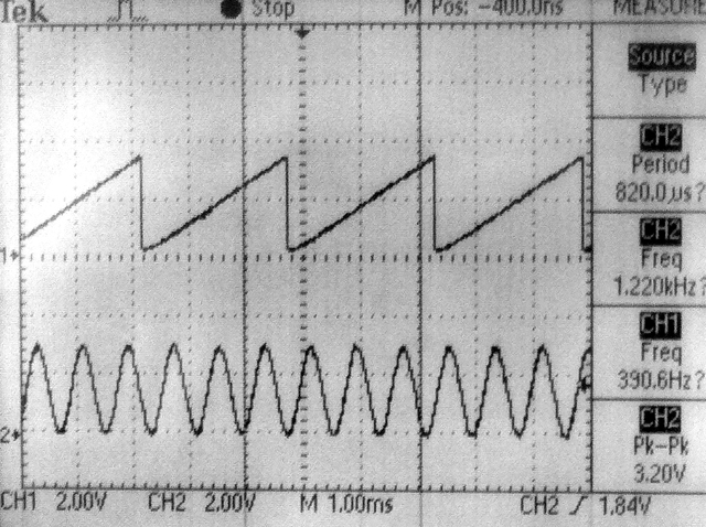
shows the SYNC on the top trace and the SCK1 on the bottom trace. The core frequency and peripheral bus frequency are set 40 mHz. The SCK1 is running at Fpb/2=20 MHz. The total transaction time for the two channels is 2.6 microSec. The second image shows the DAC outputing a DDS sawtooth on one channel and the ADC input on the other at a sampling rate of 100 KHz. Setting the core and peripheral bus to 60 MHz runs the AD7303 at its maximum bus speed and drops the total time to transmit one 16-bit transaction to 850 nS and both channels to 1.75 microSec. The code in the ISR was arranged so that all ISR housekeeping is being done while the SPI hardware does the transmit.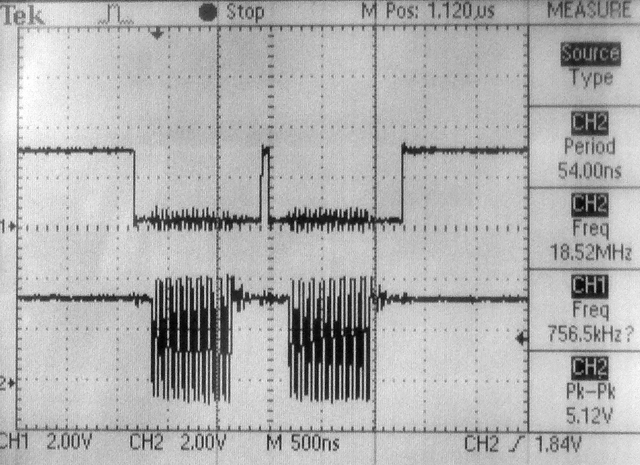
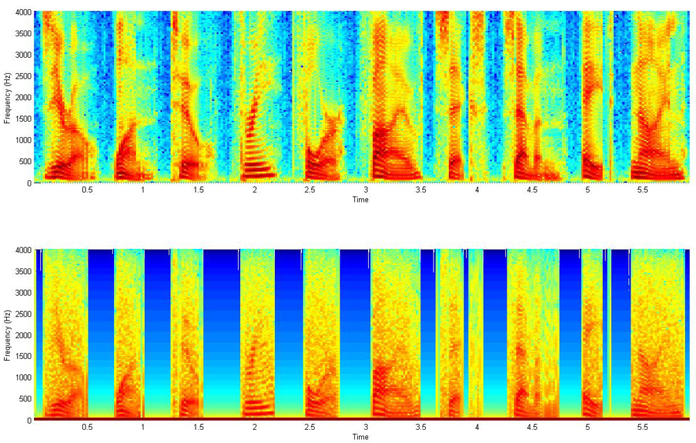
-- As shown in the section below, the Vref generator can be used as a DAC (pin 25 on PIC32MX250F128B). While 4-bits of dynamic range is not going to hack it for playing back Grateful Dead albums, it is good enough for a quick sound effect or medium quality voice production. There are several steps. First get a low dynamic range WAV file. I use the AT&T text-to-voice site to produce a WAV file with a male voice saying the digits zero to nine. Then the WAV file is processed with a Matlab program to adjust the sample rate, truncate the PCM values to 4-bits, then pack two four bit samples into each byte for storage efficiency. Next the Matlab program produces a header file of the packed samples formated so that it is loaded into flash memory. Then the playback program running on the PIC32 traverses the packed array at 16 KHz and drops the unpacked samples onto the Vref DAC. The low sample rate means that the male voices at the AT&T site sound better because we can more heavily filter and not lose too much voice content. The following image used matlab's spectrogram utility to compare the original and 4-bit quantized sounds. The top image is the 8 KHz sampled voice. The bottom image uses the signal quantized to 16 levels, then lowpass filtered with a RC filter with a cutoff of 1700 Hz. Each digit (0 to 9) is visible and the overall structure is the same, but not as crisp. The actual playback circuit used an RC filter consisitng of a 100k resistor and 1nf capacitor to get the lowpass. The quantized, filtered matlab output sounds very much like the PIC output.
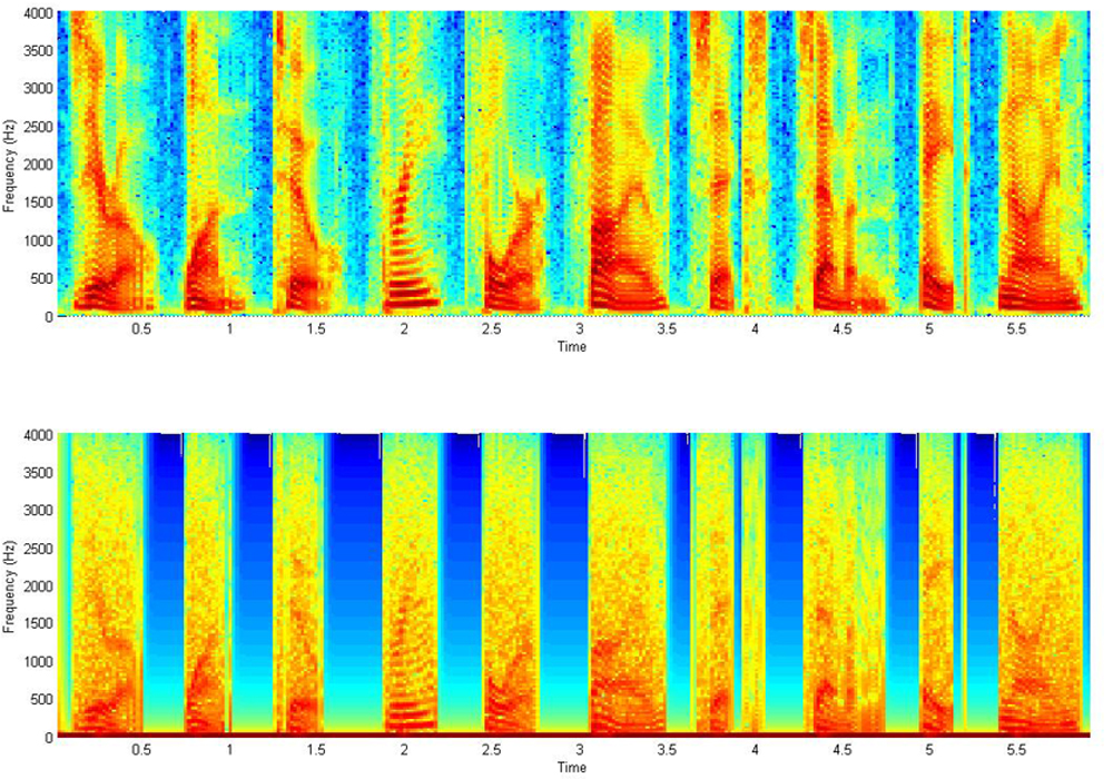
-- The 4-bit data is highly redundant. Looking at the difference between sequential samples shows that over 98% of the transitions between sequenctial samples are plus/minus one or zero. This means that if we encode the difference as a two bit number, we can make a smaller header file without losing too much information. The matlab encoder takes the differences, truncates them, resynthesises the wave from the truncated derivitive and plays the digits. Still to be done: Pack the four 2-bit difference samples into one byte and write the header file and decoder in C. The following images show the spectrogram of the raw speech after sampling to 8 kHz and the spectrogram of the waveform reconstructed from 2-bit differences.
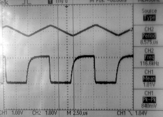
-- The Vref generator can be connected to an external pin (pin 25 on PIC32MX250F128B) and can be set to 16 values between zero and two volts. The first example generates a 16-sample square wave to investigate the settling time of the DAC. According to the Reference Manual, the output impedance at output level 0 (about zero volts) is about 500 ohms, while the output impedance at output level 15 (about 2 volts) is around 10k ohms. The first screen dump shows the Vref voltage output on the bottom trace and the same signal passed through an LM358 opamp, set up as a unity gain impedance buffer, on the top trace. Rise time (level 15) is about 0.5 microSec (to 63%) and fall time (level 0) is about 0.05 microSec. The rise/fall times are dominated by the RC circuit formed by the output impedance of Vref and the capacitance of the white board (10-20 pf) and the scope (20 pf). The LM358 is slew-rate limited and thus produces a triangle wave.
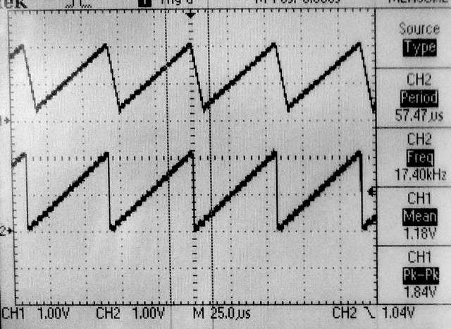
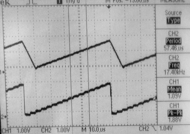
-- The next example generates a sawtooth with a period of 128 phase increments (17.4 kHz). The bottom trace is taken directly from the Vref pin, while the top trace is from the output of the unity gain LM258 follower. Notice the slew-rate limiting on the falling edge of the sawtooth.To unload the Vref pin, the output was connected to the opamp follower through a 100k resistor. A lowpass filter using the 100k resistor and a 10 pf capacitor with a time constant of around 1 microSec smooths and denoises the opamp trace (third image).
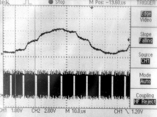
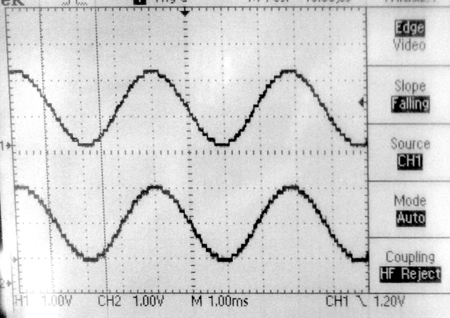
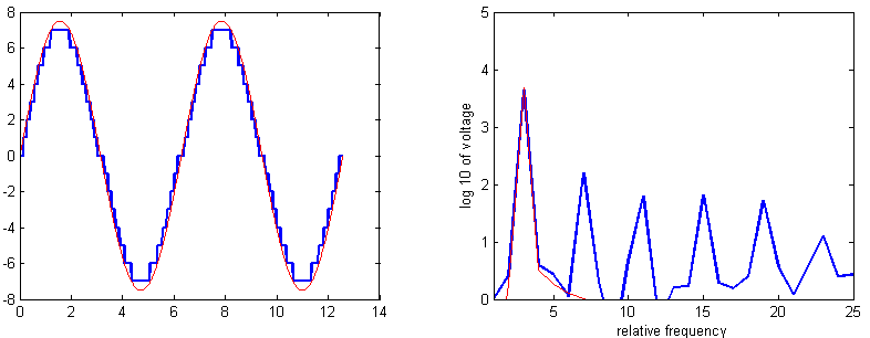
-- Any real application is going to use ISR-driven timing to output samples to the DAC. The next example uses Direct Digital Synthesis (DDS) running in an ISR at 100 kHz to generate sine waves. Tiiming the ISR using a toggled bit in MAIN, suggests that the 47 assembler instruction ISR executes (with overhead) in 1.5 microSeconds. The first image shows the DDS sine wave (but at very high frequency) on the top trace and the bit being toggled in MAIN on the bottem trace. You can clearly see the 1.5 microsecond pause in MAIN every time a new sine wave value is produced. The second image is a sine generated at Middle C (261.6 Hz). The top trace in the lowpassed opamp output. The bottom is the raw Vref pin.The code is structured as a timer ISR running the DDS. The output frequency is settable within a millHertz, but accuracy is determined by the cpu clock. Sixteen voltage levels introduces some harmonic distortion. The first error harmonic is about a factor of 30 in amplitude below the fundamental and at 3 times the frequency. This is in line with Bennett for 4-bit signals. The matlab image shows the full and 16-level sampled sine waves on the left and their spectra on the right (code). Listening to the signal gives a sense of very high frequency spikes. Lowpass filtering with a time constant equal to about 1/(sample-rate) gets rid of most of the sampling noise..