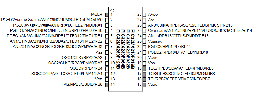
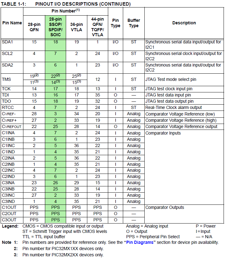
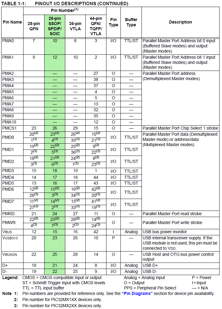
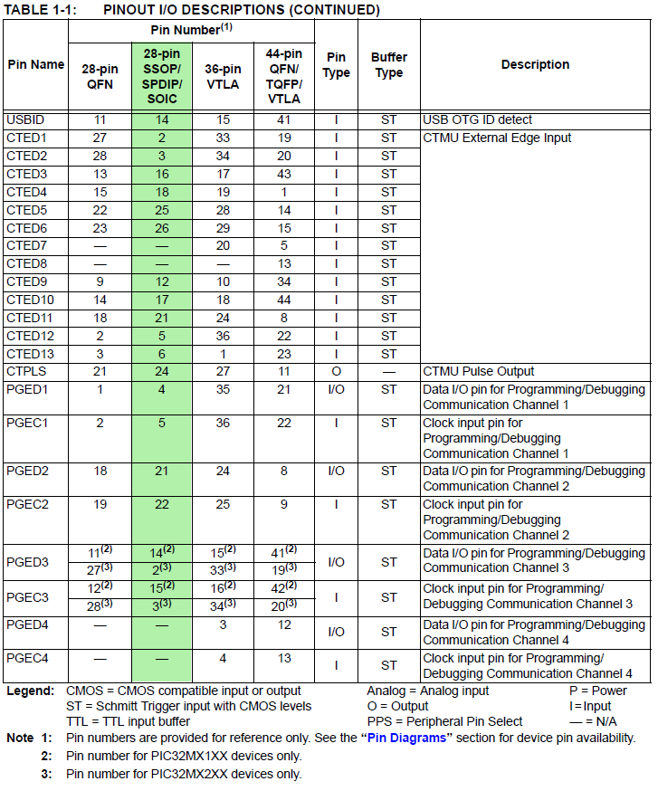
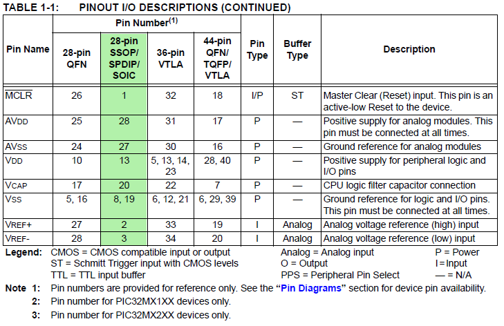
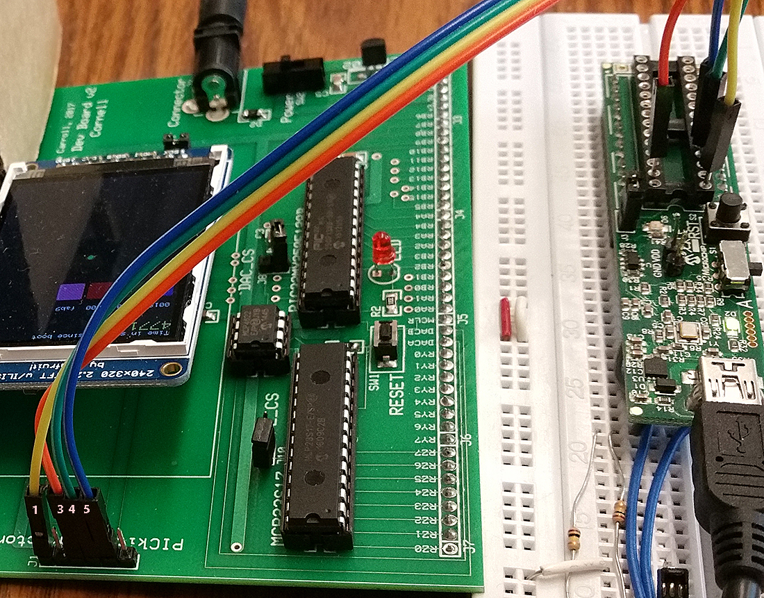
When you click on the images below, you will get enlargments with the pin numbers indicated.
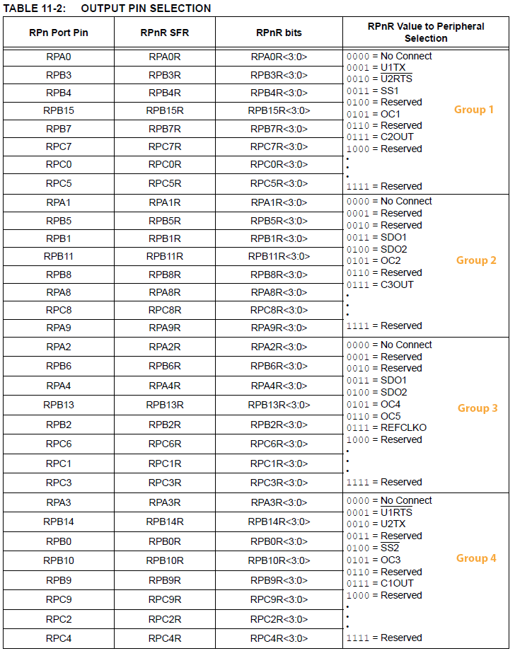
You will produce a music synthesizer, played using a keypad, and with a programmable playback function. But first you need to set up a board, arrange jumpers, learn how to connect peripheral devices and use the compiler. I strongly suggest that you use some of the time during the first lab exercise to build your own PIC32 board, which you can then keep, but if you wish you can borrow one. Once you do that, the MicrostickII will be the programmer for the new board.
Examples:
Karplus-Strong algorithm String Synth, Thanks to Linda Alexander, Julia Hesterbrink, Nathan Zimmerberg.
Hardware
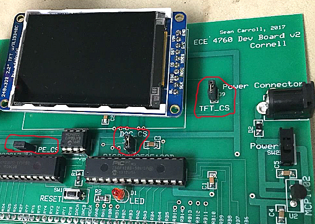
The Big Board which you will build features a port expander, DAC, TFT header-socket, programming header-plug, and power supply.
See the construction/testing page for specific code examples of each device on the big board.
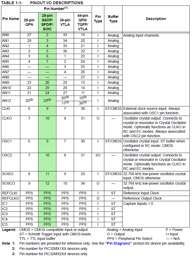
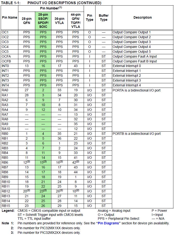
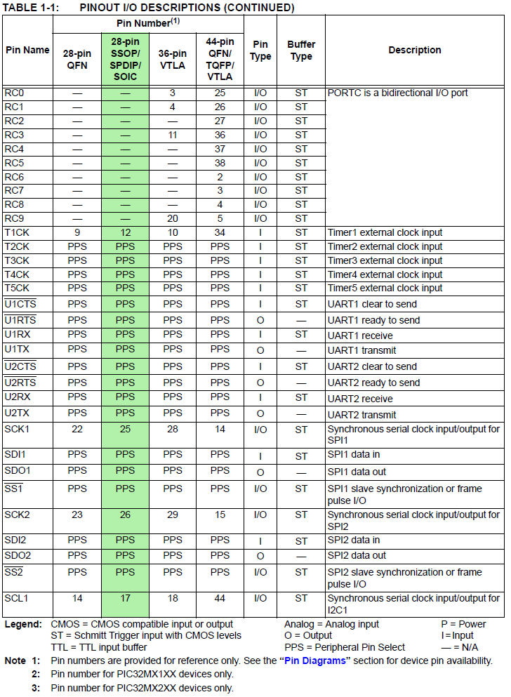
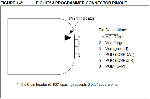
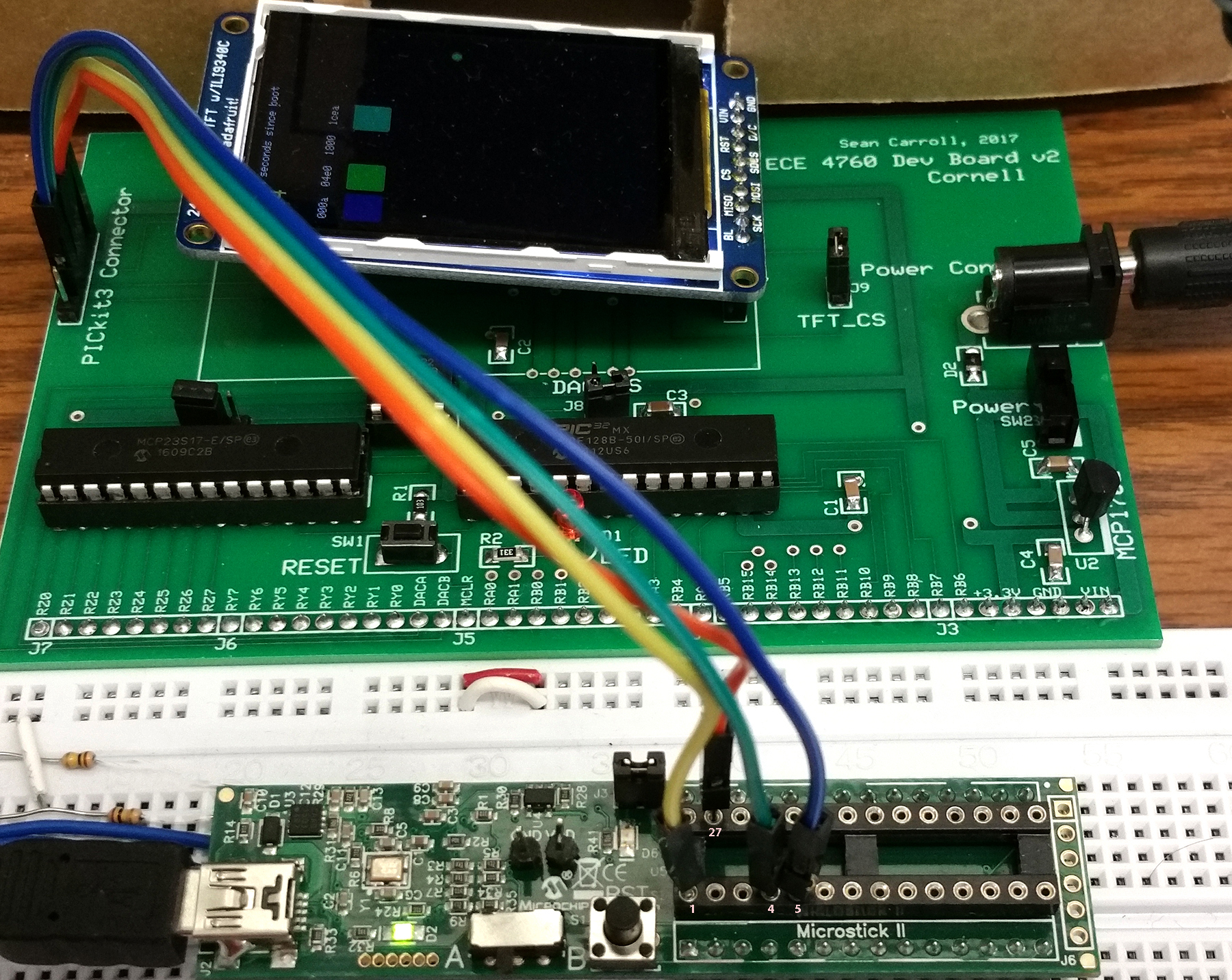
The connections from the PIC32 to the various peripherials is determined by the construction of the board. The list is repeated here.
PIC32 i/o pins used on big board, sorted by port number. Any pin can be
recovered for general use by unplugging the device that uses the pin.
SPI chip select ports have jumpers to unplug.
----------------------------
RA0 on-board LED. Active high.
RA1 Uart2 RX signal, if serial is turned on in protothreads 1_2_2
RA2 port expander intZ
RA3 port expander intY
RA4
PortExpander SPI MISO
-----
RB0 TFT D/C
RB1 TFT-LCD SPI chip select (can be disconnected/changed)
RB2 TFT reset
RB4 DAC SPI chip select (can be disconnected/changed)
RB5 DAC/PortExpander SPI MOSI
RB6 !!! Does not exist on this package!!! (silk screen should read Vbus)
RB9 Port Expander SPI chip select (can be disconnected/changed)
RB10 Uart2 TX signal, if serial is turned on in protothreads 1_2_2
RB11 TFT SPI MOSI
RB12 !!! Does not exist on this package!!! (silk screen should read Vusb3.3)
RB14 TFT SPI Sclock
RB15 DAC/PortExpander SPI Sclock
----------------------------
But note the few silk-screen errors on the board.
SECABB version 2 silk screen errors. (fixec on version 2.1)
--Edge connector pin marked RB6 -- RB6 Does not exist on this package! Silk screen should read Vbus.
--Edge connector pin marked RB12 -- RB12 Does not exist on this package! Silk screen should read Vusb3.3.
--LED D1 outline -- Silk screen should have flat side should be oriented toward PIC32.
Software
Software you will use is freely downloadable and consists of:
More information
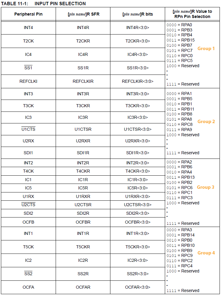
PPSInput(2, U2RX, RPB11); //Assign U2RX to pin RPB11 -- Physical pin 22 on 28 PDIP PPSOutput(4, RPB10, U2TX); //Assign U2TX to pin RPB10 -- Physical pin 21 on 28 PDIP Microstick2 as a programmer
The connections to the microcontroller socket on the Microstick2 act like the standard programming signals from the PICKIT3, the programmer which was used to develop the boards you will build. On both the big and small board, J1 marks pin1 of the 6-pin ICSP header.
| Signal | PICkit3 (ICSP) connector on board |
Microstick2 DIP Pins |
|---|---|---|
| MCLR | 1 | 1 |
| ground | 3 | 27 |
| prog data (PGD) | 4 | 4 |
| prog clock (PGC) | 5 | 5 |
A wiring example is shown below. Note that pin 1, MCLR, is only available on the Microstick2 DIP socket as shown.
When you click on the images below, you will get enlargments with the pin numbers indicated.
Procedure
OpenChoice Desktop in the start menu, and start the program. Select Instrument.USB device, and click OK.Get Screen.Keypad connection
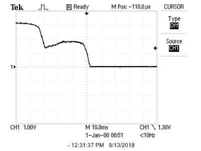
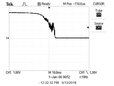
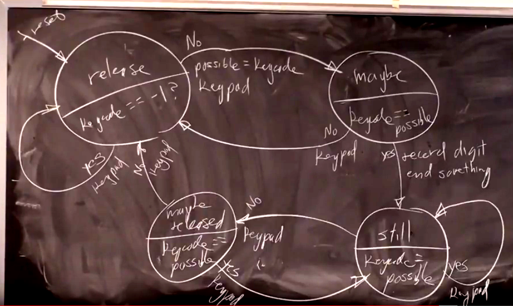
The keypad page shows how to hook up the keypad to the port expander. Again, refer to DDS_Accum_Expander_BRL4.c, on the Development board page for an example that handles the port-expander, keypad, and DAC. This code is written assuming that the keypad is connected to the port expander! If for some reason you decide to connect the keypad directly to the MCU, the code must be changed.
DAC and audio output
The SPI DAC you will use is the MCP4822. The DAC analog output is marked DACA or DACB on the SECABB
The SPI connections are supplied on the Big Board (SECABB), as long as you connect the DAC_CS jumper.
Section 5.1 and 5.2 of the MCP4822 datasheet discussed the way the the DAC uses SPI.
The edge connector pin marked DACA or DACB will go (optionally through a low pass filter) to an audio socket, to be connected to the green audio plug of the speakers. If you are going to design a lowpass filter for the DAC, then you need to know that the input impedance of the speakers is around 10 Kohm.
Audio socket ![]() . The pin nearest the socket is ground. Wire the left/right channels together.
. The pin nearest the socket is ground. Wire the left/right channels together.
Speaker audio input plug ![]() The body of our plugs are green.
The body of our plugs are green.
Musical notes
See the Suggested Background problems for the specifications on frequency, harmonic distortion, and envelope shaping. Generally speaking you want to make pleasant sounding synthesis. You may want to look at the sound synthesis page, but you should use linear envelopes (example 1), rather than exponential (example 2). I suggest starting with a linear attack of about 1000 samples, a sustain of about 1000 samples and a decay of 10000 samples. You are going to use either additive (Fourier) or FM synthesis to build interesting sounds. Near the bottom of the older AVR DSP page is a list of additive synthesis parameters for different sounds. The newer sound synthesis page has parameters for FM synthesis.
A table of note frequencies is below. If you prefer, you may use a higher or lower octave.
But if you go to a lower octave, the little speakers may not have much response below 200 Hz:
C4 262 Hz (middle C)
D4 294
E4 330
F4 349
G4 392
A4 440
B4 494
C5 523
Program Organization
I suggest that you organize the program as follows:
PT_YIELD_TIME_msec(30), then repeats. PT_YIELD_TIME_msec(10), then repeats.You may find some of previous year's lectures useful. Particularly lectures 2, 3, 4.
Debugging
If your program just sits there and does nothing:
--
Did you turn on interrupts? The thread timer depends on an interrupt.
-- Did you write each thread to include at least one YIELD (or YIELD_UNTIL, or YIELD_TIME_msec) in the while(1) loop?
-- Did you schedule the threads?
-- Did you ask to initialize the TFT display in the code, while not having a TFT on the board?
-- Does the board have power?
If your program reboots about 5 times/sec:
--
Did you exit from any scheduled thread? This blows out the stack.
-- Did you turn on any interrupt source and fail to write an ISR for that source?
-- Did you divide by zero? A divide by zero is an untrapped exception.
-- Did you write to a non-existant memory location, perhaps by using a negative (or very large) array index
-- Did you use single quotes to define the FORMAT string in a PRINTF statment
.
If your thread state variables seem to change on their own:
--- Did you define any automatic local variable? Local variables in a thread should be static.
-- Are your global or static arrays big enough the clobber the stack in high memory? You should be able to use over 30kbytes.
Week one required checkpoint
By the end of lab session in week one of the lab you must either have
built and tested your own board or tested a prebuilt board.
Week two required checkpoint
By the end of lab session in week two of the lab you must have:
Week three Assignment
Timing of all functions in this lab, and every exercise in this course will be handled by interrupt-driven counters, not by software wait-loops.
ProtoThreads maintains a ISR driven timer for you! This will be enforced because wait-loops are hard to debug and tend to limit multitasking.
Write a Protohreads C program which will:
When you demonstrate the program to
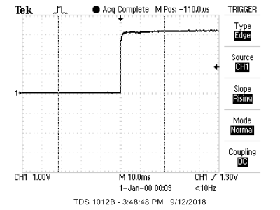
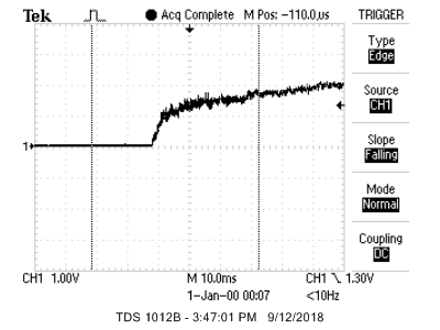
a staff member, you should demonstrate all three modes, the accuracy of the note frequencies using the scope, and record and play back a sequence of notes. One possibility for demo is below, but you can play any tune you like. At no time during the demo can you press reset, or reprogram the MCU.
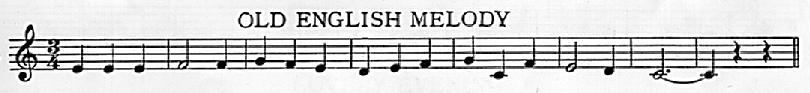
Notes: E  E  E | F  F  |  G  F  E | D  E  F | G  C  F | E  D |  C  C
Play the hollow notes twice as long as the filled notes.
Your written lab report should include the sections mentioned in the policy page, and :