|
|
|
|
||
|
|
ECE5760 Final Project Adaptive Noise Cancellation Demo: Simulated Channel |
|
||
|
|
||||
|
|
||||
|
|
|
|
|
|
|
|
||
|
|
The main action of the adaptive FIR filter shown in Figure 1 is to track the
channel impulse response so that the background noise can be subtracted from
the primary input. The channel interference can be complicated because of
the delays and amplitude attenuations caused by the enviroment. Therefore,
for a more complicated channel interference, more filter weights should be
instantiated on FPGA. In this particular simulation scheme, the
channel interference is simulated in MATLAB by using different types of FIR
filters. The numer of weights of the adaptive filter on FPGA is 8 for all
experiments and simulations unless noted otherwise.
|
|
|
|
||
|
|
|
|
|
|
|
The reference noise and primary input stay the same
The channel impulse response used for generating Figure 5 (FPGA Implementation) is a band pass filter: Channel=[0.5 -0.25 -0.5 0.125]; The adaptive noise canceller works fine for the band pass filter.
The reference noise and primary input stay the same
The channel impulse response used for generating Figure 6 (FPGA Implementation) is a notch filter: Channel=[0.5 0.5 0.5 0.5]; Figure 6 shows that the performance of the adaptive filter for the low pass/notch channel is less impressive as for other channels. The reason is that this channel clearly boosts the noise-to-signal ratio and therefore even with a good noise reduction gain the noise won't decrease to a low level.
In order to furthur illustrate how the channel influence the performance of the adaptive noise canceller built on the FPGA, the frequency responses of each channel used before are shown in Figure 7, Figure 8, Figure 9, and Figure 10.
The adaptive filter on FPGA performs well for the first three filters while it doesn't effectively reduce the noise when the interferer channel is a deep notch and high gain low pass filter. The reason for causing this problem is two fold. First, the deep notch filter significantly removes the white noise between 2000kHz and 3000kHz and the adaptive filter then fails to filters out the corresponding noise from the voice signal due to limited calculation accuracy. However, the voice signal can still be recovered perfectly in MATLAB because of its high calculation accuracy. Secondly, the high gain in low frequency bands increases the noise-to-signal ratio and worsens the performance of the noise canceller. Test One: Voice Recovering "Hello"   The reference noise and primary input stay the same The channel impulse response used for generating Figure 3 (FPGA Implementation) is an all pass filter: Channel=[1 0.5 -0.25 0.125 -0.125 0.025]; The corresponding MATLAB simulations are not repeated for this and the following cases in Simulation One. This is because that MATLAB always seems to perfectly recover the source. Figure 4 shows that the FPGA implementation of the adaptive filter with 8 weights is still able to track the channel and negate its influence on the source.
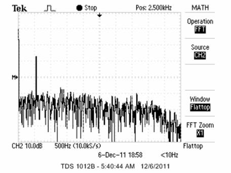
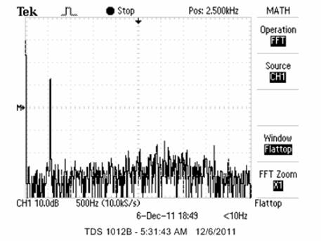
Figure 11: The FFT of filter input and filter output
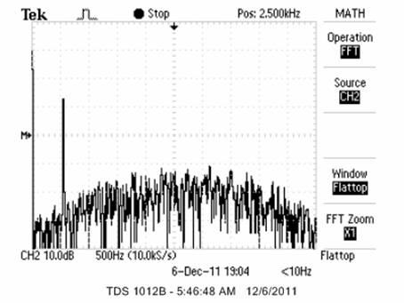 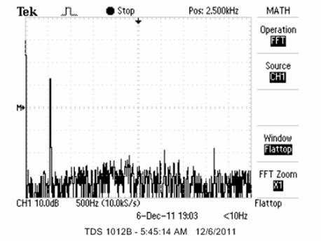
The test is repeated with a band pass channel instead of an all pass channel. It is shown in Figure 11 that the noise reduction gain is between -15dB and -20 dB across the whole frequency band.
The purpose of the test two is to find out the noise reduction gain of the noise canceller by using a single sinusoid as the desired signal source instead of the voice. The reference noise is still the white noise for worst scenario noise cancellation. The channel for generating the results shown in Figure 11 is an all pass channel. Figure 11 shows that the adaptive noise canceller can provide a -15dB noise reduction on average across the whole frequency band. This means that the noise can be reduce to 1/10~3/10 of its original level.
Figure 11: The FFT of filter input and filter output for an all pass channel
Test Two: Noise Reduction Gain  Figure 10: Low pass/notch channel
Figure 9: Band pass channel 
Figure 8: Low pass channel 
Figure 7: All pass channel 
Filters to Simulate the Channel: 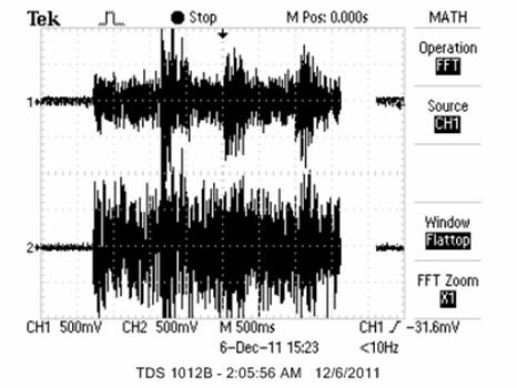
Figure.6: low pass/notch
channel
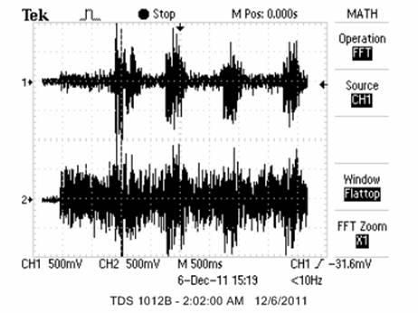
Figure.5: band pass channel
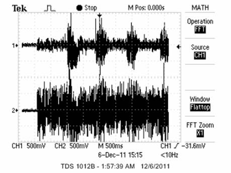
Figure.4: low pass channel
The reference noise, primary input for simulation one "voice recovering" are as follows: Signal=Voice saying "Hello" which is prerecorded. Noise=0.1*1*(rand(1,itno+4-1)-0.5); which is simulated in MATLAB Channel one on the oscilloscope is the filter output and channel two is the filter input. This setting stays the same for the rest of experiments unless noted otherwise. The channel impulse response used for generating Figure 2 (MATLAB simulation) and Figure 3 (FPGA Implementation) is an all pass filter: Channel=[1]; As can be shown in Figure 3, the FPGA can efficiently reduce the noise strenght to a level that "hello" can be clearly heard.
Figure.3: All pass channel 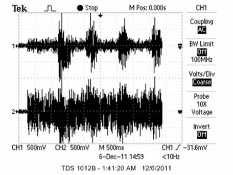
Figure.2: MATLAB simulation results for an all pass channel
Figure.1: Block diagram of the adaptive noise
canceller
 |
|
|
|
|
|
©2011 The School of Electrical and Computer Engineering, Cornell
University
|
|
|
|
|