Logical Structure
Parallelism
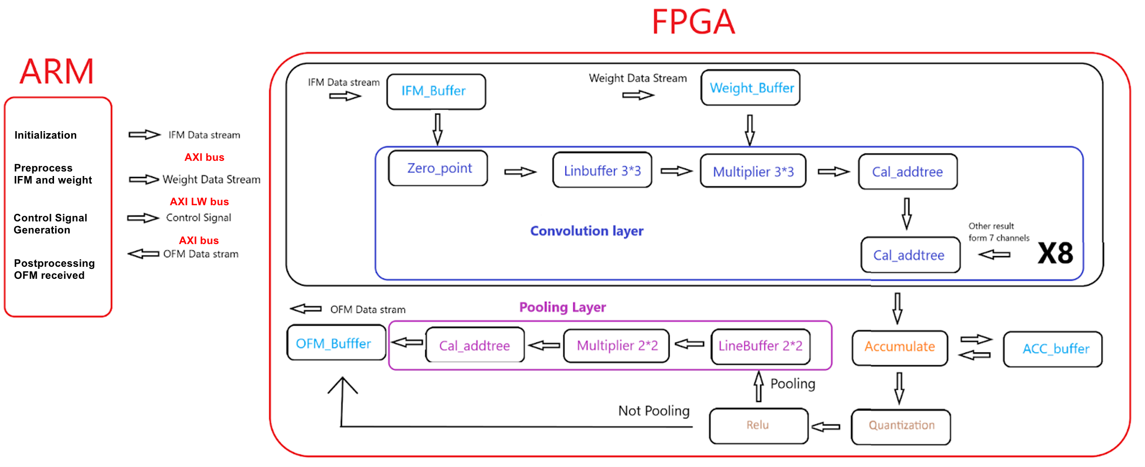
The high-level design architecture is shown below in Figure 5. Firstly, as mentioned before, FPGA is excellent at parallel computation, so formulating an appropriate scheme that defines the parallelism strategy in detail is important. Considering the limited resources on the DE1-SoC board, especially for block memory and DSP, it’s infeasible for us to increase the degree of parallelism as much as we want. So, we decided to parallelize 9 multiplication within the convolution kernel and 8 input channels, which means the Multiply-Accumulate Operations (MACs) within one single cycle that can be achieved is 2*8*9 = 144.
ARM
For the ARM side, HPS will send the corresponding input feature maps and weights of 8 channels in order before controlling the accelerator to start inference of the CNN, and when one output feature map is completed, the accelerator will send the corresponding output feature map back to HPS via Advanced eXtensible Interface(AXI).
Accelerator Design and Trade Offs
For the FPGA fabric, there are four different kinds of buffers to store intermediate data, including:
- IFM_Buffer: storing input feature maps of 8 input channels.
- Weight_Buffer: storing weights of 8 input channels.
- ACC_Buffer: storing accumulation data of one output channel.
- OFM_Buffer: storing the output feature maps of one output channel.
For the accelerator's backbone, first, the accelerator will access IFM_Buffer based on the read address sent from the HPS side. Then, the accessed data will be loaded into a line buffer with a length twice the size of the padded input feature map of the current layer after subtracting the quantization zero point of the input data from it. When the warm-up stage of the line buffer has been completed, the corresponding 3*3 weight window will be fetched from the weight buffer to participate in the multiplication and addition with the 3*3 IFM window generated from the line buffer. Then, the MAC result of 8 input channels will be added together where we used two adder trees. At this point, the convolution result of 8 input channels will be temporarily stored in the ACC_Buffer, which will be fetched later when the next 8 input channels have completed the convolution. The accumulation result is not valid until the last group of input channels finishes convolution at the “Accumlate” stage. When the accumulation result is valid, the data after quantization and ReLU modules can be written into the OFM_Buffer. However, if the current layer demands a max-pooling operation, the accelerator will enter the “Pooling Layer” before being written into the OFM_Buffer. So, there is a 2-to-1 MUX to select the write data of the OFM_Buffer based on whether performing pooling or not. Lastly, when all of the data of one output channel is written into OFM_Buffer, the accelerator will send the output feature map of this output channel back to HPS for the inference of the next layer.