Software Design
Main Function
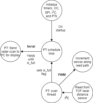
The main function consists of the setup and initialization of all of our timers, our PWM channels for our servos, the I2C channel, the protothreads and scheduler, the serial channel, and the sensor. In this function, two protothreads are added to the scheduler: the timer thread and the dataread thread. Our send_data thread is used to send the radar data to the python backend from the PIC. Our dataread thread is used to pan our robot back and forth and collect distance readings while doing so.
VL53L1X Library
One of the core structural choices we made for this project was to port the Sparkfun Arduino library for this sensor over to the PIC32. This library, in turn, implemented the STMicrocontrollers API for the chip. We viewed the API implementation as unnecessarily specific for us to learn while the arduino level library interfaced with the hardware at a level that was more consistent with this class. This was also a very worthwhile exercise because porting libraries from one architecture to another is a skill that will be directly applicable in future projects. With this library specifically, we found that all of the functions were sensor specific except for the very base unit of I2C reading and writing that was specific to the arduino. By changing this base unit to PIC32 I2C commands instead of arduino, we only had to make minimal changes to the rest of the library to get it to work. We found this approach to be really effective and still taught us a lot about the sensor and how I2C works at a low level.
Debugging
We found a timing issue in the I2C_Write()'s that was accidentally solved with our debugging print statements. Ref 5 in the Appendix shows a table that lists the "Bus free time between transmissions" to be 1.3ms. It turns out, with the vast numbers of print statements we had written to diagnose the problem, we had accumulated over 1.3ms of delay between transmissions. Upon commenting them out since the problem was solved, we no longer were able to read the distance. After extensive debugging and a good deal of paranoia, we replaced the prints with delays to isolate the problem to a timing issue, then found this figure in the datasheet. Knowing the cause, we finally solved this issue by adding a delay(2) to both the I2C read and write commands to impose this down time requirement on the bus.
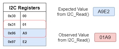
One key tool we used in the debugging process was the Picoscope. The Picoscope was instrumental in allowing us to see how the I2C interface was working. The scope has a feature on it that will decode the signals on the I2C bus and show what addresses the PIC is reading or writing from and what information is being written or read. This was an invaluable tool because it allowed us to check that the physical signals being sent were correct compared to what we could see on the serial output. At one point in our project, we were getting correct reads with our I2C but the serial print statements showed that there was a shift in the I2C reads: our first read would get a 0 from the bus, then the next read would get the value from the first address we were reading from. This issue was resolved on the C end as the I2C was shown to be working properly on the Picoscope.
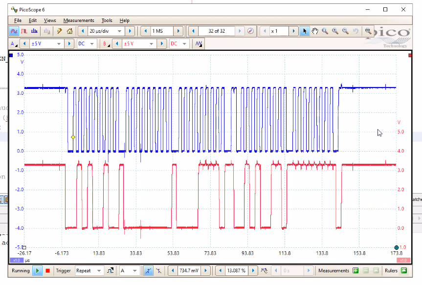
This is how our debugging on the picoscope started - counting bit by bit. We later saved I2C settings to the scope and used the built-in interpreter
The other key strategy we used to test this system was to set up an additional sensor with an arduino at home. Because of the remote work environment we weren’t able to interact directly with the hardware, making it difficult to understand certain things about the sensor. By hooking up an identical sensor to an arduino running the arduino library that we ported over, we were able to see how the sensor and the library was supposed to work. This also allowed us to test out different features of the library before we copied them over like messing with the region of interest (ROI) and the sample rate. It is of note that the hardware setup we had at home was deliberately not the same as the setup we accessed remotely. We decided to set up a simplified system at home to fill in the gaps of what we could test and play around with using the remote system.